

Sensor systems is one of the highest growing and upcoming segments in the semiconductor market. Sensors have a vast array of applications in electronics, industrial automation, avionics and military, mobile devices, consumer electronics, building and infrastructure, medical equipment, security, transportation, IT infrastructure and communication among others.
Sensor technology is evolving consistently and relies on numerous leading-edge technologies to deliver improved functionality required by industries worldwide.
Sensor technology is driven by key factors such as low cost, chip level integration, low power and wireless connectivity. Advancement in technology and miniaturization of devices has driven the market growth in recent times. High demand in consumer electronics and automotive industry has positively impacted the market demand owing to numerous applications of sensors in these sectors.
In addition to factors such as time to market and price sensitivity posing a challenge, the fluctuating global economic conditions could hinder the sensor market
In 8 weeks, we will welcome 30 leading industry speakers to the second sensor event, Sensor Solutions International. (26-27 March, Brussels) These innovators of industry will speak on themes covering application and developments in Transportation, Flight, Health, Imaging and Energy to name a few.
To support the event, the first issue of our quarterly title Sensor Solutions will address key issues in the industry and report on the ever-changing dynamics of this growth market.
This issue is packed with features, with contributions from companies such as, Toposens, who describes “Next-level 3D Ultrasound Sensor Based on Echolocation”; Lightricity on a “PV Energy Harvesting solution”; InvenSense who looks at “The Growing Role of Sensors in the IoT/IIoT”.
Bosch discusses “Sensors and artificial intelligence” and Analog Devices explains the demands on sensors for future servicing. We would also like to thank Euroicc for their piece on “Smart thermostats”; Claytex for Sensor models for virtual testing of autonomous vehicles “and ams AG for “AI in Sensors for IoT”

If you would like to be considered for the next issue, please contact me on Jackie.cannon@angelbc.com
Jackie Cannon
In a H2020-project MIREGAS, Technical Research Centre of Finland VTT Ltd and Tampere University of Technology teams, together with European partners, developed novel components for miniaturized gas sensors exploiting the principle of Mid-IR absorption spectroscopy. In particular, the main advances concerned the development of novel superluminescent LEDs for 2.65 µm wavelength, Photonic Integrated Circuits (PICs) with 1nm bandwidth for spectral filtering at Mid-IR, hot-embossed Mid-IR lenses for beam forming and photodetectors for 2 to 3µm wavelengths. Silicon photonics PIC technology that was originally developed for optical communication applications allows for the miniaturization of the sensor. The components entail important benefits in terms of cost, volume production and reliability.
The market impact is expected to be disruptive, since the devices currently on the market are typically complicated, expensive and heavy instruments. The components developed by the consortium enable miniaturized integrated sensors with important benefits in terms of cost, volume production and reliability, which are instrumental features for the wide penetration of gas sensing applications.
The IR spectroscopy is a powerful tool for multigas analysis. Conventional sensors are based on the use of filters, spectrometers or tuneable lasers. MIREGAS project, has introduced breakthrough components, which enable multigas analysis using integrated solution. Moreover, using the new technology, the wavelengths of light can be filtered more precisely, and interfering gas components can be excluded.
H2020 European consortium, MIREGAS, brought together world-leading European institutes and multinational companies. On the technology side, VTT Technical Research Centre of Finland Ltd coordinated the programme and provided Si PICs as well as photonics packaging and integration technologies. The Optoelectronics Research Centre at the Tampere University of Technology in Finland was responsible for developing innovative superluminescent LEDs, ITME (PL) for mouldable Mid-IR lenses and VIGO (PL) for Mid-IR detectors. Industrial partners Vaisala (FI), AirOptic (PL) and GasSecure (NO) brought their competences in the areas of gas sensing and Mid-IR sensor fabrication, and at the same time, validated the technologies developed by the consortium.
"The project will enable us to extend our gas sensing technology into new market areas. The MIREGAS technology offers a unique mix of sensitivity, selectivity and competitive pricing that will be a complement to our present high-performance, laser-based sensing technology. Airoptic plans to a release a first product for hydrocarbon detection based on the technology developed within the MIREGAS project in 2019", says CEO Pawel Kluczynski from Airoptic.
"Bearing in mind the potential market for devices developed in the MIREGAS project, VIGO System SA has started to implement a development plan that assumes investments in increasing technological and production capacities - which will allow for the future, high volume production of sensors based on SLED sources. The main actions of the plan are the purchase of a high-performance epitaxial machine, the expansion of the assembly capabilities and the acquisition of specialists in the field of epitaxial materials for the production of IR sources," stated Chief Sales Officer Przemysław Kalinowski from VIGO.
"Within this project, ITME was able to establish technology for low-cost mid IR optics development using moulding optics approach. We have developed several novel glasses transparent from visible up to Mid-IR range. We establish moulding processing that allow us to develop free-form optical components with optical surface quality for Mid-IR without further polishing. It allows to reduce cost of production first, but also to develop lenses in environment friendly matter since number of glass waste is dramatically reduces. Also grinding and polishing process that requires use of large amount of water and polishing powders is totally redundant. We found also new materials for mould development that are low cost and can be processed with standard CNC machines. This way our technology becomes cost effective also for prototyping and short series of components. This breakthrough give access for custom made free-form glass optics even for SME companies," says Prof. Ryszard Buczynski, head of Department of Glass, ITME. "Now we verify market potential of our technology and offer access to this technology as a custom service through ITME. After market validation, we plan to transfer this technology to other existing companies or establish spin-off company. Some venture funds and world-recognized companies already expresses their interest in our innovations."
"At the start of the project, Mid-IR SLED technology targeting high-brightness and broadband operation was simply not existing. MIREGAS enabled important scientific breakthrough; in fact, the project results represent the state-of-the-art both in terms of power and wavelength coverage. Yet, what it is maybe the most important, contributed to creating a new European ecosystem based on combined expertise in Mid-IR optoelectronics and Si-photonics. We are just at the start of many other applications we will target with this powerful combination of technologies", adds Prof. Mircea Guina, the head of ORC team at Tampere University.
"VTT's Silicon-on-Insulator (SOI) based Photonic Integrated Circuit (PIC) technology owns two unique features: Firstly, in addition to the conventional optical communications wavelengths at 1550 nm, it is applicable for Mid-IR wavelengths; Secondly, it allows for the integration of active devices, such as, laser diodes or photodetectors, directly on the PIC chip. Therefore, the SOI PIC technology is very attractive for gas sensing and sensor integration, in general. In the MIREGAS project, we were able to take this offering to the next level together with the beneficiaries", stated Pentti Karioja, VTT, project coordinator.
.
A new sensor fusion technique based on X-ray and 3D imaging promises improvements to the 3D modelling of mineral resources and more efficient sorting of precious metals. VTT Technical Research Centre of Finland Ltd (VTT) is coordinating the sensor development process through an EU project called X-Mine in collaboration with businesses, international research institutions and mining lobbies.
The European Commission has granted EUR 9.3 million to a three-year H2020 project coordinated by VTT called X-Mine, which develops new sensor technologies for mining companies' drill core analyses and for efficient sorting of precious minerals and metals in ore. The X-Mine project also promotes more efficient 3D modelling of mining companies' mineral resources, and thus improved recovery of precious minerals. The project combines products developed by various sensor manufacturers with commercial ore dressing equipment and aims to achieve sensor fusion that allows rock with low levels of minerals to be separated from the ore. The project reached its midway point at the turn of the year and is progressing gradually to the piloting of both drill core analysers and ore dressing equipment at mines during the spring of 2019. Two drill core analysers were adopted at mines in Greece and Sweden towards the end of 2018, and members of the project consortium are currently testing new sensors for ore dressing equipment and designing ore dressing algorithms. The project consortium consists of 15 research partners and businesses from around the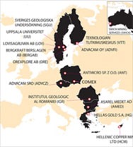
Figure 1. a) Project consortium, b) Members of the consortium on a visit to Kęty in Poland to learn about the development of ore dressing equipment at a demonstration event hosted by Comex
The project gives the participating research institutions and businesses an opportunity to develop sensor-based solutions for the mining industry together with experts specialising in the exploitation of ore resources, mineral processing and geological mapping. The consortium's aim is to develop solutions for efficient ore extraction and for reducing the amount of waste generated by the ore extraction process. All in all, the project is expected to reduce the harmful environmental impacts of mining by reducing the need for ore processing and chemical processing in mineral recovery. The project consortium is also looking to lower mining companies' production costs.
The X-Mine project involves developing and piloting two prototypes to meet mining companies' needs. Mining companies extract material from the bedrock in order to analyse the location of the ore and the volume of minerals and to estimate their mineral resources. The project consortium is hoping to increase the efficiency of ore exploration by developing equipment that can be used to scan drill core samples on site using new, highly sensitive layered imaging technology based on X-ray fluorescence as well as composition analyses. Analysing and scanning drill core samples on site speeds up the evaluation of ore resources.

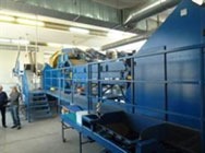
Figure 2. a) A drill core analyser developed by Orexplore b) Prototype of ore dressing equipment to be built in Comex's research environment
The project also expects to improve the operation of automated mineral selectivity systems at the extraction stage by establishing a sensor fusion technique that combines X-ray transmission scanning along a line of highly sensitive sensors developed in the course of the project, X-ray fluorescence technology and 3D vision technology with rapid analyses with the help of efficient algorithms. More efficient ore dressing increases resource efficiency and mining companies' profitability while reducing the harmful environmental impacts of mining.
The project was granted funding through the Horizon2020 instrument – the EU's research and development programme that has EUR 80 billion to award to European research initiatives over a seven-year period (between 2014 and 2020). The EU's H2020 funding programme promises more breakthroughs, discoveries and world-firsts by taking great ideas from the lab to the market. The total budget for the three-year project is EUR 11.9 million, of which EUR 9.3 million comes from the European Union.
The X-Mine project is based on international cooperation between research institutions from Finland (VTT), Sweden (Uppsala University, Geological Survey of Sweden) and Romania (Geological Institute of Romania) as well as sensor and equipment manufacturers from Finland (Advacam Oy), Poland (Antmicro Sp. z o. o. and Comex Polska Sp. z o. o), the Czech Republic (Advacam s.r.o.) and Sweden (Orexplore AB). End users involved in the project include mining companies in Bulgaria (Assarel Medet Jsc.), Greece (Hellas Gold S.A.), Cyprus (Hellenic Copper Mines Ltd) and Sweden (Lovisagruvan AB) as well as mining lobbies in Sweden (Bergskraft) and Australia (Swick Mining Services Ltd).
Sensirion is a manufacturer of environmental as well as gas and liquid flow sensors. The cost-effective LD20 single-use liquid flow sensor, which has been used for this concept study, is compact and measures flow rates in the micro and milliliter per hour range with outstanding precision and reliability thanks to the patented CMOSens Technology. Additionally, it features sensitive failure detection mechanisms to help counteract, for example, occlusions and air-in-line. Quantex is an innovative leader in single-use disposable pump technology. The pump’s design is based on a rotary, fixed displacement principle thus is much less sensitive to variables such as line pressure, fluid viscosity and flow rate.
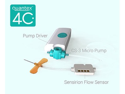
The new wearable drug delivery IoT platform “Quantex 4C” demonstrates an innovative approach to infusion therapies. It integrates connectivity with a modular drug delivery platform and enables continuous monitoring of the therapy with the help of a single use liquid flow sensor for safe ambulatory treatments. “Real time bidirectional flow verification at the low flow rates that are typical for the targeted application and the sensor’s compact form factor made the Sensirion LD20 single-use liquid flow sensor the ideal choice”, said Paul Pankhurst, Founder and CEO of Quantex. The objective of the presented study is to demonstrate the possibilities of a comprehensive drug delivery system to the medical technology industry. The compactness, low power consumption and cost-effectiveness of both, sensor and pump, allow the design of a wearable device which controls and monitors the drug delivery therapy simultaneously. Such a connected drug delivery platform opens up entirely new possibilities for all involved stakeholders. While patients and clinicians benefit from an increased ease of use and confidence in the therapy, low maintenance and less training efforts; it allows healthcare and pharma companies to capture vital adherence data and simplifies patient compliance.
Reliable failure detection is a central requirement for next generation drug delivery devices. Ambulatory treatments and wearable applications will only be successful if patients as well as clinicians trust the reliability of those next generation devices.
Redsense Medical announces that the company has started the development of a prototype with fully functional optical measuring based on the innovative, smart wound technology that was presented in November 2018. The prototype is expected to be ready in Q2 2019.
The company's smart wound care technology makes it possible to develop thin sensor layers for optical measuring of several physiological and biological parameters such as blood and exudate. The layer of sensors can be used separately or integrated directly into smart bandages or adhesive plasters. As the technology enables very cost and resource effective individual wound care, it has potential to become as revolutionary for wound care.
"We have now decided to go from TRL 2 to TRL 3 on NASA's readiness level indicator for development projects, and it will be very exciting to present a working prototype before the start of the summer," says Redsense Medical's CEO Patrik Byhmer.
As announced earlier, Redsense has already initiated discussions on potential collaborations or out-licensing of the technology with large, global wound care companies. The discussions are expected to intensify and become more concrete when a working prototype can be presented and evaluated.
Redsense will present ongoing project updates during the coming months as substantial progress is expected. Based on this outlook, the smart wound care technology has the potential to build substantial value for Redsense Medical´s shareholders.
Strong outlook for the wound care market
The wound care market was valued at approximately USD 18 billion in 2016, and it is expected to grow at a CAGR of 5.3 % until 2023. The primary drivers of market growth are an ageing global population, a larger number of diabetics and increasing investments in research and development, which is also expected to lead to new research discoveries in this area. Chronic wounds are expected to constitute most of the wound care market up until 2022.
The Internet of Things (IoT) is creating many new exciting application opportunities to create smart environments where sensors monitor for changes so that the appropriate actions can be taken. The fastest growing examples of this are HVAC (Heating Ventilation and Air Conditioning), IAQ (Indoor Air Quality), smart homes and smart offices where a network of sensors monitors temperature and carbon dioxide (CO2) levels to ensure the optimal conditionals are maintained with the minimum of energy expenditure. A challenge for such systems in that the CO2 sensors need mains power to operate incurring costs for cabling and, in the case of installing in existing buildings, redecoration.
Gas Sensing Solutions (GSS) has solved this problem with its low power, LED-based sensor technology. The sensor’s power requirements are so low that wireless monitors can be built that measure CO2 levels as well as temperature and humidity with a battery life of over ten years. Being wireless means that they can be placed wherever they are required with no need for cabling or disruption and simply relocated as building usages changes
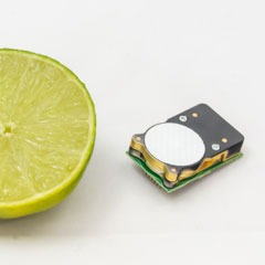
CO2 Detector with Lime
To make the design of these monitors even easier, GSS has added an I2C interface to its very low power CO2 sensor, the CozIR-LP. Having the widely used I2C interface now makes the integration of the sensor into a design very easy. The CozIR-LP is the lowest power CO2 sensor available requiring only 3mW that is up to 50 times lower than typical NDIR CO2 sensors. The GSS patented LED technology also means that the solid state sensor is very robust. This keeps maintenance costs to a minimum as the expected lifetime is greater than 15 years making them the perfect choice for fit and forget applications that measure low (ambient) levels of CO2 from 0-1%.
“Although HVAC and IAQ are major application areas,” explained Calum MacGregor, CEO at GSS, “the lightweight, miniature size of the CozIR-LP also opens up other new possibilities for CO2 monitoring such as portable and wearable devices. The power requirements are so low that energy harvesting designs, such as solar, are now easily achievable. Here again, the new feature of an I2C interface will simplify the design process of integrating the sensor with other sensors and devices all on the I2C bus.”
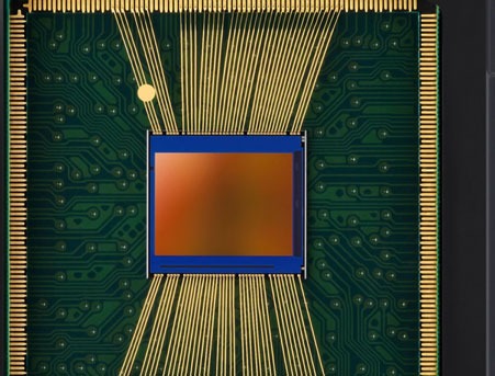
Samsung introduces its smallest high-resolution image sensor, the ISOCELL Slim 3T2, said to be the industry’s most compact 20MP image sensor at 1/3.4-inches. The 0.8μm-pixel ISOCELL Slim 3T2 is aimed to both front and back cameras in mid-range smartphones. The 1/3.4-inch 3T2 fits into a tiny module making more space in ‘hole-in or notch display’ designs.
“The ISOCELL Slim 3T2 is our smallest and most versatile 20Mp image sensor that helps mobile device manufacturers bring differentiated consumer value not only in camera performance but also in features including hardware design,” said Jinhyun Kwon, VP of System LSI sensor marketing at Samsung Electronics. “As the demand for advanced imaging capabilities in mobile devices continue to grow, we will keep pushing the limits in image sensor technologies for richer user experiences.”
When applied in rear-facing multi-camera settings for telephoto solutions, the 3T2 adopts an RGB color filter array instead of Tetracell CFA. The small size of the image sensor also reduces the height of the tele-camera module by around 7% when compared to Samsung’s 1/3-inch 20MP sensor. Compared to a 13MP sensor with the same module height, the 20Mp 3T2 retains 60% higher effective resolution at 10x digital zoom.
The Samsung ISOCELL Slim 3T2 is expected to be in mass production in Q1 2019.
The incident at London Gatwick airport in the UK caused major travel disruption for more multiple days after drones were spotted flying over this sensitive area. This incident highlighted the need for anti-drone technologies to address this evolving threat and secure the safety of flight. Following the episode, the US Federal Aviation Administration was instructed to develop a strategy to allow wider use of counterdrone technologies across airports. Detecting drones, and any UAV threat is a real challenge for many reasons. HGH Infrared Systems with its family of renowned SPYNEL thermal sensors offers a unique set of solutions to address this evolving threat and ensure true, real-time airport security.
In these times of heightened UAV threats, the SPYNEL IR imaging camera provides an innovative solution which guarantees the ability to detect, track and classify any types of drones.
Whereas the drone technology is constantly evolving, bringing on the market many different types of drones including fixed wing, multi rotor drones, drones with GPS, autopilot and camera, autonomous drones emitting low or no electromagnetic signature, the SPYNEL thermal imaging technology, makes it impossible for a UAV to go unnoticed: any object, hot or cold will be detected by the 360° thermal sensor, day and night. Driven by the CYCLOPE intrusion detection software, the panoramic thermal imaging system tracks an unlimited number of targets to ensure that no event is missed over a long-range, wide area surrounding. SPYNEL is thus fully adapted to multi-target airborne threats like UAV swarming. SPYNEL is a versatile, multi-function sensor with a large field of view enabling real-time surveillance of both airborne and terrestrial threats at the same time.
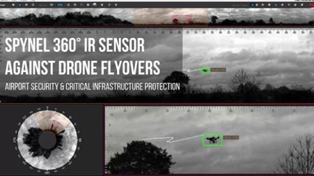
The CYCLOPE automatic detection software provides advanced features to monitor and analyse the 360° high resolution images captured by SPYNEL sensors. The ADS-B plugin enables aerial target identification and the aircraft ADS-B data can be fused with thermal tracks to differentiate an airplane from a drone. With the forensics analysis offering a timeline, sequence storage and playback possibilities, it is also possible to go back in time to analyse the behaviour of the threat since its first apparition on the CYCLOPE interface. Moreover, the latest CYCLOPE feature makes 3D passive detection by triangulation available when using several SPYNEL sensors at the same time. The feature consists in analyzing the distance and the altitude of multiple targets, creating a kind of "protective bubble" around the airport.
Edouard Campana, Sales Director at HGH Infrared Systems, said: "Spynel 360° panoramic thermal camera and its Cyclope software are frequently used against drones to ensure the security of national and international events, critical infrastructures, airport and more. The real-time visualization and detection of multiple targets makes it a unique sensor for ultimate situational awareness. This solution is rapidly deployable and offers HD playback capabilities, very useful for events clarification.”
A key advantage of the SPYNEL detection system for airport applications is that it is a fully passive technology, meaning it will not be a source of disturbance in the electromagnetic environment of the airport, unlike radars. Indeed, a concern often raised by air-safety regulators is that anti-drone systems designed to jam radio communications could interfere with legitimate airport equipment.
Part of the complete surveillance equipment of an airport, the SPYNEL thermal imaging sensor is the must have security equipment for such a high-risk infrastructure, operating with complementary detection sensors. Military facilities, correctional institutions, stadiums and other critical infrastructures have already chosen to integrate the SPYNEL sensor with their other security and facility systems, such as radars, PTZ cameras, Video Management System and more. SPYNEL can also be rapidly deployed as a standalone solution for temporary surveillance, to face urgent cases. With its 24/7 and panoramic area surveillance capabilities, the SPYNEL thermal camera provides an early warning and an opportunity for rapid and accurate detection over large areas, to support proactive decisions.
The MLX90340 is an absolute position sensor based on the Melexis Triaxis Hall technology targeted for various applications in consumer and industrial markets. With a key set of core parameters, the MLX90340 addresses the essence: simple and robust position sensing. It offers the best flexibility to measure a 360 degrees rotational (end-of-shaft or through-shaft) and up to a +/- 20 mm linear magnet movement.
This new device consists of a Triaxis® Hall magnetic front-end, an analog to digital signal conditioner, a DSP for advanced signal processing and one output stage driver. Due to the Integrated Magneto Concentrator (IMC), it is sensitive to magnetic flux in three planes (X, Y & Z) enabling the design of non-contact position sensors with an Analog or PWM output.
The MLX90340 is available in both a single die (SOIC-8) and fully redundant dual-die (TSSOP-16) package for safety-critical applications. It will complement the successful automotive grade MLX90365 by adding three different temperature ranges for cost-effective applications.
Additionally, Melexis offers four pre-programmed versions customized for various rotation ranges. These provide an analog voltage from 10% to 90% of the supply voltage over an angle span of 90, 180, 270, or 360 degrees, avoiding the need for additional programming at the customers’ side and enabling embedded designs where the power ground and output pins are not accessible.

See why Edge use single point loadcells for converting retail space into sales
By Kim Paulussen - Marketing Specialist, Zemic Europe B.V.
Single points used for realtime retail analysis on the spot
EdgeNPD offers innovative SaaS (Software as a Service) solutions with state-of-the-art tools to help retailers and manufacturers increase sales and ROI from retail space with minimum cost and risk. theStore2 Retail Lab software is a VR enabled 3d application for optimising planograms, POSM and space management, allowing for prototyping and testing future trade, marketing or in-store communication strategies. The solution facilitates faster and better decisions driven by advanced data analytics. The full-stack model allows clients to outsource the entire process necessary to manage the category efficiently - from market research, through analytics and decision making, with implementation and training of sales teams.
Edge NPD’s underStand is an Internet of Things hardware and software solution for both retailers and manufacturers. It is a weight sensor-based, cloud connected device which collects and processes data from POS in real time. UnderStand reports and analyses rotation and out of stock data from your promotional activities allowing to separate regular and promotional sales and gain full control over your secondary placement. UnderStand can be used for pre-testing future- or monitoring current promotions allowing to optimize replenishments and sales rep visits.
This goal of Edge NPD solutions matches very well with Zemic’s vision. As we strongly believe that our focus on creating value for our customers will help them to differentiate themselves in their market. Zemic Europe's slogan is therefore "We believe we make you stronger!".
Zemic & Edge NPD
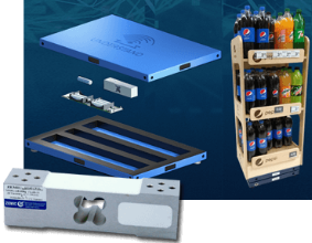
How Zemic consulted EDGE NPD
For the concept "Edge IoT underStand" which EDGE NPD developed, monitoring sales is the most important feature. Not only to detect when a product is bought by a consumer; but more importantly to monitor the product & turnover flow in order to optimize the retail store. All monitoring features of the "Edge IoT underStand" concept are meant to create the most optimum and efficient retail store. This is how space is converted into sales.
To have an accurate and reliable result EDGE NPD searched for a reliable partner which could supply a large number of single point loadcells in a relatively short time. Zemic Europe offered, with their european warehouse with 40.000 products in stock, the right combination of fast delivery together with the right quality/price/service ratio. This enabled EDGE NPD to act quickly and professionally, assisting their customers' needs within the fast moving consumer goods branch.
About underStand from EDGE NPD
EDGE NPD is the laureate of the 2017 edition of the New Europe 100 list. This is a listing of outstanding innovators in Central and Eastern Europe.
Edge underStand has the following benefits for retailers :
1. underStand requires no involvement from the store – it can be installed on a variety of stands and can provide both stand-based or shelf-based monitoring
2. underStand makes it easy to organize and monitor promotions in real time so you can estimate future profits instantly
3. the unique architecture of underStand allows you to monitor parameters such as the effectiveness of shelf product distribution
4. underStand is integrated in all Edge systems: theStore, Geo, ProPOSe, VideoAnalysis, and Trade Planner
Zemic Europe L6E single point loadcell for retail concept.
Single Point Load Cells are often installed in most small to medium sized platform scales. The L6E aluminium load cell is used for the "underStand" concept of Edge NPD. This is an aluminium alloy IP65 single point loadcell suitable for platforms up to 400 x 400 mm. The L6E family is available in OIML C3 , C4 and C5 accuracies in capacities from 50kg up to 300kg.
For more information:

Zemic Europe is a leading manufacturer and designer of loadcells, strain gages and force sensors. We are here to help our European customers with all enquiries and assisting them with their challenges. With 34 years of being active in the field of weighing you can expect from us a professional technical support for your application and we can give you advice for the “best fit” load cell, mounting hardware, strain gage or pressure and torque transducer.
Our Head office in Europe is based in The Netherlands from where we stock thousands of products which can be delivered within 1 day to anywhere in Europe. Zemic Europe can also offer you your own private label with or without OIML approvals. If our wide range of standard products does not meet your requirements our engineering staff of over 225 engineers is ready to design a special product according to your specifications.

The Internet of Things (IoT) is now already reality in multiple application areas. Smart sensors used in smart cities, autonomous driving, home and building automation (HABA), industrial applications, etc. experience challenging requirements in large interconnected networks.
A significant increase of data transmission and required bandwidth, leading to an overload of the communication infrastructure can be expected.
To mitigate this, the use of artificial intelligence (AI) in smart sensors can significantly reduce the amount of data exchange within the networks. Philipp Jantscher from ams AG explains.
Artificial Intelligence (AI) is not a new topic at all. In fact, the idea and the name AI, already appeared in the 1950s. People started to develop computer programs to play simple games like Checkers. One milestone known to many people was the launch of the computer program ELIZA, built in 1966 by Joseph Weizenbaum. The program was able to run a dialog in written English. It created questions, the user provided an answer and ELIZA continued with another question related to the response provided by the user.

Figure 1: Example screenshot of the ELIZA terminal screen
The main AI technique are neural networks. Neural networks have first been used in 1957 when Frank Rosenblatt invented the perceptron. Today’s neurons in neural networks are still using a very similar principle. However, the capabilities of single neurons were rather limited. It took until the early 70s before scientist realized that multiple layers of such perceptrons could overcome these limitations. The final breakthrough on multi-layer perceptron was the application of the backpropagation algorithm to learn the weights for multi-layer networks. An article in Nature in 1986 by Rumelhart et. al.[Rum] made backpropagation mark the breakthrough of neural networks. From this moment, many scientists and engineers were drawn into the neural network hype.
In the 1990 and early 2000, the method was applied to almost any kind of problem. The number of research publications around AI, and particularly neural networks, significantly increased. Nevertheless, once all the magic behind neural networks has been understood, it became just one of many other classification techniques. Due to their very demanding training efforts, neural networks in the second half of the 2000 decade faced significantly reduced interest.
Reinvestigating neural networks with respect to their operating principles caused the second hype, currently still ongoing. By having more computational power at hand and the involvement of a large number of people, Google demonstrated to beat the best Go players with a trained neural network.
Types of AI's
Over the last decades, different AI techniques have emerged. In fact, it is not black and white whether a certain technique belongs to AI. Many simple classification techniques like principle components analysis (PCA) also use training data. They are not classified as AI however. Four very prominent techniques are outlined in the subsequent sections. Each of them has many variants and the given overview in this article does not claim to be complete.
Fuzzy Logic
Fuzzy Logic extends classic logic based on false/true or 0/1 by introducing states that are in between true and false, like “a little bit” or “mostly”. Based on such fuzzy attributes it is possible to define rules for problems. For example, one of the rules to control a heater could be the following: “If it is a little bit cold, increase the water temperature a little bit”. Such rules seem to express the way humans think very well. That is why Fuzzy Logic often is considered an AI technique.
In the real application, large sets of such fuzzy rules are applied to control problems for instance. Fuzzy Logic provides algorithms for all the classical operators like AND, OR and NOT to work on fuzzy attributes. With such algorithms, it is possible to infer a decision out of a set of fuzzy rules.
A set of fuzzy rules has the advantage of being easily read, interpreted and maintained by humans.

Figure 2: Example for fuzzy states of a heater control. The arrows denote the state values at the indicated temperature
Figure 2 illustrates the fuzzy states of a heater control. The states are “Cold”, “Warm”, and “Hot”. As can be seen in the figure, the three states do have some overlap and some temperatures belong to two states at the same time. In fact, each temperature belongs to a certain state with a defined probability.
Genetic Algorithm
Genetic Algorithms apply the basic principles of biological evolution to optimization problems in engineering. The principles of combination, mutation and selection are applied to find an optimum set of parameters for a high dimensional problem.
Assuming a large (more than 20) set of parameters with a given fitness function, it is mathematically not possible to determine an optimum set of parameters to maximize the fitness function.
Genetic Algorithms tackle this problem in the following way. First, a population of random parameter sets is generated. For each set in this population, the fitness function is calculated. Then the next generation is derived from the previous generation by applying the following principles:
Each set of the next generation is then evaluated using the fitness functions. In case one set appears to be good enough, the genetic algorithm stops, otherwise a new generation is created as described above.
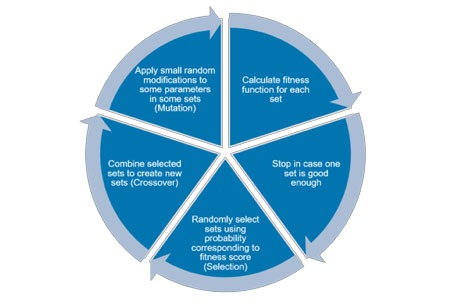
Figure 3: Description of generating algorithm cycle
It has been shown that for many high-dimensional optimization problems a Genetic Algorithm is able to find a global optimum, whereas conventional optimization algorithms fail, because they were stuck in a local optimum.
Genetic Programming
Genetic Programming takes Genetic Algorithms a step further by applying the same principles to actual source code of programs. The sets are replaced by sequences of program code and the fitness function is the result of executing the actual code.
Very often, the generated program code does not execute at all. It has been demonstrated however that such a procedure can indeed generate working source code for problems like finding an exit in a maze.
Neural Networks
Neural networks mimic the behavior of human brains by implementing neurons. They take input from many other neurons, and then perform a weighted sum. Finally, the output is limited to a defined range. The impact of a specific input depends on the weight associated to this input. These weights resemble the functions of synapses in the human brain to a certain extent.
The weights of the connections are determined by applying inputs and desired outputs. This again is very similar to the way humans teach their kids how to determine the difference between a dog and a cat.
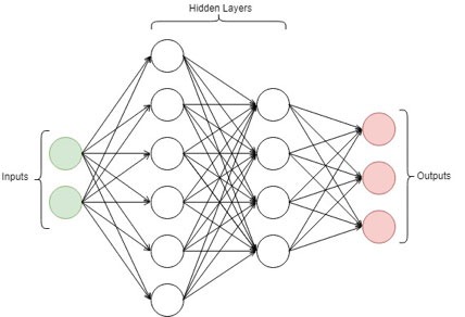
Figure 4: Example of a neural network architecture
The main components of a neural network architecture are input nodes where the input data is applied. The second set of components are hidden layers who process the inputs through application of weights to their inputs. The weighted inputs are then transferred to the inputs of the next layer. Finally, the outputs assign a certain weight to the classification of the input set as a result.
Local Intelligence
IoT sensor solutions today are mostly only responsible for data acquisition. The raw-data needs to be extracted from the sensor and transmitted to another, more computationally capable device within the network. Depending on the use-case, this device could be either an embedded system, or a server within the cloud. The receiving end collects the raw-data and performs pre-processing in order to present relevant results. Frequently the raw-data of the IoT device needs to be processed using artificial intelligence, as in speech recognition for example. The amount of IoT devices and especially the demand for artificial intelligence is expected to increase dramatically over the next years since sensor solutions become more complex.
However, the growing amount of connected IoT devices, which rely on cloud solutions to compute meaningful results, leads to various problems in several areas. The first issue is the latency between acquiring the raw-data and the response with the evaluated information. It is not possible to build a real time system, since the data needs to be sent over the network, processed on a server and then again interpreted by the local device. This leads to the second problem, which is the increasing network traffic and therefore is reducing reliability of network connections. Servers need to handle more and more requests of IoT devices and thus could be overwhelmed in the future.
A major advantage of neural networks is their ability to extract and store the essential knowledge of a large set of data in a fixed, typically much smaller set of weights. The amount of data, which is used to train a neural network, can be vast. In particular, for high dimensional problems the data set needs to scale exponentially to maintain a certain case coverage. The training algorithm extracts the features out of the data, which efficiently will classify unseen input data. As the number of weights is fixed, the amount of storage does not correlate to the size of the training data set. For sure, if the network is too small it will not deliver good accuracy, but once a proper size has been found the amount of training data does not affect the size of the network anymore. Nor does it affect the execution speed of the network. This is another reason why in IoT applications a local network can outperform a cloud solution. The cloud solution may of course store vast amounts of reference data, but then the response time of the cloud degrades quickly with the number of reference data stored in the cloud.
By definition, IoT nodes are connected to a network, and very likely to the Internet. However, it can be very desirable to have a local intelligence. Then, processing of raw data can happen on the sensor or in the IoT node instead of requiring communication with the network. The most important reason for such a strategy is the reduction of energy consumption of network communication traffic.
Major companies as embedded microprocessor manufacturers already realized, that cloud-based services have to be adopted. One of the consequences is the introduction of new embedded microprocessor cores capable of machine learning tasks. In the future, the trend of processing data within the cloud will be further shifted back to local on-device processing. This allows more complex sensor solutions, which involve sensor fusion or pattern recognition. For these applications, local intelligence of the IoT device is needed. Sensor solutions will become truly smart, as they already deliver finalized meaningful data.

Figure 5 represents this paradigm shift from cloud-based solutions, to local intelligence.
However, computing elaborate AI solutions within an IoT device, requires new solutions which meet power, speed and size constraints. In order to archive this, the trend is shifting to integrated circuits optimized for machine learning. This type of processing is commonly referred to as edge AI.
Constraints
In sensors for IoT applications, which are very frequently mobile or at least service free, the most prominent constraint is power consumption.
This leads to a system design, which minimizes the amount of data to be transferred via a communication channel as sending and receiving data. In particular, in wireless mode, transmission is always very expensive in terms of power budget. Thus, the goal is to process all raw data locally and only transmit meaningful data to the network.
Local processing neural networks are a great option as their power consumption can be well controlled. First, the right architecture (recurrent versus non-recurrent) and the right topology (number of layers and neurons per layer) must be chosen. This is far from trivial and requires experience in the field. Second, the bit-resolution of the weights get important. Whether a standard float type is used or whether someone can find an optimized solution using just 4 bits per weight contributes significantly to memory size and therefore to power consumption.
Gas Sensor Physics
The sensor system, used as a test case for AI in sensors, is a Metal-oxide (MOX) based gas sensor. The sensor works based on the principle of a chemiresistor[Kor]. Under a certain possible set of reducing (e.g. CO, H2, CH4) and/or oxidizing (e.g. O3, NOx, Cl2) gases the detector layer is changing its resistivity. This can in turn be detected via a metal electrode sitting underneath the detector layer. The main problem of such a configuration is the indiscriminate response to all sorts of gases. Therefore, the sensor is thermally cycled (through a microhotplate). This causes the sensor to react with a resistance change with a unique signature and thus significantly increases the selectivity of gas detection.
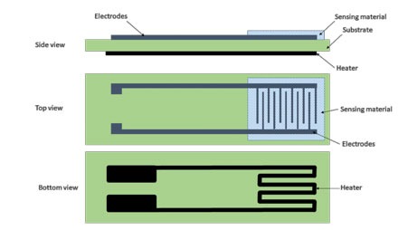
Figure 6: Structural concept of a chemiresistive gas sensor
Another approach is to combine different MOX sensor layers to discriminate further between the different gas types.
A closed physical model explaining the behavior of chemiresistors would depend on too many parameters. A non-exhaustive list of these parameters are thickness, grain size, porosity, grain faceting, agglomeration, film texture, surface geometry, sensor geometry, surface disordering, bulk stoichiometry, grain network, active surface area, size of necks of the sensor layer. Together with the thermal cycling profile, the model would be too complex and is currently simply not available.
Therefore, such systems form an ideal case to apply modern AI methods.
Supervised Learning
Gas sensing is an especially potent application for AI. The problem, which needs to be solved, is the prediction of the concentration of gasses with the resistance of multiple MOX pastes as the inputs.
To solve the task, the behavior of the MOX pastes when exposed to various gasses with different concentrations has been recorded. From this data, a dataset consisting of features (the temporal resistance trend of each paste) and labels (the gas that was present) has been created.
This kind of data is especially well suited for the supervised learning method. In supervised learning, the neural network is given many samples, each consisting of features and a label. The network then learns to associate features with labels in an iterative learning process. It is exposed to every sample multiple times. Its prediction is nudged in the direction of the correct label every iteration by adjusting its weights.
Architecture and Solution Approach
A neural network is defined by its architecture. The architecture is usually influenced by the dataset at hand. In our case, the dataset has a temporal structure, so a recurrent neural network is a good fit. Recurrent neural networks process the features in multiple steps and keep information about previous steps in an internal state.
The architecture also has to be adapted to the already mentioned IoT constraints. The neural network should be as small as possible to minimize power consumption. We use one hidden layer with 47 neurons. The weights are quantized to 4 bits, which further reduce power consumption. On top of this, the network is implemented in an analog circuitry to make it even more efficient.
The network was first tested in a pure software environment using TensorFlow (https://www.tensorflow.org/). This allowed rapid adjustment of the architecture to make sure it is able to solve the task properly before actually building it.
Results
It is not trivial to evaluate a machine learning classifier. There are multiple ways to measure performance. One of the most popular ones is the Receiver Operating Characteristic (ROC). The ROC is a line with false positive rate on one axis and true positive rate on the other. The area under the curve (AUC) of this line should be as high as possible. It measures how well the classifier can separate the positive and negative samples.
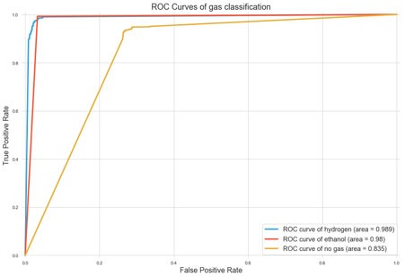
Figure 7: Correlation of false positives to good positives for the example of ROC classified gas data
Another interesting metric is the mean absolute error (MAE). The MAE averages the absolute error of the prediction over all samples. We have been looking at this metric over time to get a sense of how many time steps the network needs to achieve a good prediction.
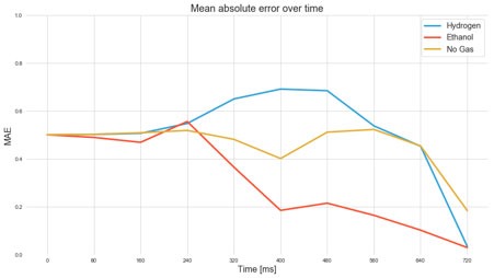
Figure 8: Development of MAE metric over time of a neural network trained on the gas sensor data
Systems where AI could be relevant
This section gives an overview of possible future sensor solutions. In general it can be assumed, that reading raw-data from sensors will not be sufficient anymore, since the complexity and capability of sensors themselves is increasing.
The raw-data needs to be heavily computed and/or combined with the raw data of other sensors to deliver a meaningful result. This method is called sensor fusion. Often, all sensors required for the task, are already included in one solution including an embedded system. Using AI, sensor fusion can be done much easier and more accurately than with classical algorithms. Neural networks can cope with unknown situations much better. In addition, it can detect compensation techniques given the training data and potentially increases the value of the delivered result to the customer.
For our example, classical algorithms would require physics based models, which are not available.
Another example, where the usage of AI is the state-of-the-art solution is object recognition within a camera image. This area has huge potential within the sensor industry.
It allows for small wirelessly connected IoT devices, which are reporting detected objects immediately, anywhere throughout the building without the need of cloud processing.
This could spawn sophisticated surveillance solutions, presence detection or even enable things like smart fridges, which recognize the type of grocery inserted into it.
In addition, facial recognition in embedded devices and smartphones are a trending topic. Here, the facial recognition could be directly performed within the IoT device, creating a plug-and-play solution for customers.
Another area are sensor hubs, which are IoT devices collecting information of other sensors and cameras within the network. Using AI, these devices are capable of identifying patterns, routines and make pro-active steps in support of the customer.
This allows new applications within home automation, which are currently not possible.
Privacy and Data Protection
Typical IoT devices provide no protection against reverse engineering. Therefore, any data, which is stored as a standard firmware on a micro controller in a sensor node, must be regarded as public. Very often, the algorithm to infer meaningful information from sensor raw data is an important asset of sensor providers.
Neural networks do not store the data, which has been used for training. Instead, they extract the relevant features of the data and store these features in the set of weights. It is just impossible to reverse this data extraction and storage operation. This means even given all the weights of a network it is not impossible to derive even parts of the original data, which has been used for training.
This is an important property of neural networks. In particular, in the area of biometry where training data is always a large set of very personal data like face images or fingerprints. Neural network based systems can use such data without any problems of privacy and data protection after the training phase has been finalized.
Summary & Conclusions
This article has shown the increasing importance of AI within sensors in IoT systems. The history of AI and its types was introduced, which lead to the use cases within sensor solutions. It was shown, why AI has a strong potential for sensor solutions in the future and it was demonstrated using the example of gas sensing applications. A prototype implementation for this example including the results was presented. In the end, possible future applications were discussed.
The importance of privacy though protection of the data is very important and cannot be ignored in future systems. Shifting the intelligence back to the IoT device instead in the cloud allows for better selection of data, which need to be processed by third parties.
[Rum] Rumelhart, David E.; Hinton, Geoffrey E.; Williams, Ronald J. (1986-10-09). "Learning representations by back-propagating errors". Nature. 323 (6088): 533–536.
[Kor] Korotcenkov, Ghenadii “Handbook of Gas Sensor Materials – Properties, Advantages and Shortcomings for Applications Volume 1: Conventional Approaches”, Springer 2013, ISBN 978-1-4614-7164-6
http://northstream.se/insights/blog/the-convergence-of-ai-and-iot-are-we-there-yet/
https://developer.arm.com/products/processors/machine-learning

We already live in the age of smart devices, yet the future seems to be even more ‘’smart’’.
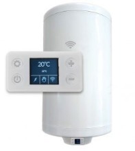
The future of the water heater industry lies in the energy efficient, smart and connected devices. The water heater will be an integral part of the smart home. The market is already familiar with the smart water heater concept, but this product category is still in its early stage.
What is a smart water heater?
There are several answers to this question. We will try to provide the most commonly used definitions.
The first one is related to the concept of ‘’smart devices’’ and the Internet of Things (IoT), meaning they are being connected to the internet and remotely controlled via mobile devices (i.e. mobile phone or tablet). This image of the smart water heater is represented worldwide, especially in the USA.
The other is related to the implementation of Artificial Intelligence (AI) concept in the HVAC industry. This means that besides the water heater can be easily programmed, it can even learn user’s behavior and prepare hot water when needed, based on user preferences. This optimizes energy usage and leads to cost reduction. This definition of the smart water heater is commonly used in Europe thanks to the EU’s very clear regulations regarding home appliances. The European Commission has issued several directives and introduced the phrase ‘’smart control’’ – which means ‘’that device can automatically adapt the water heating process to individual usage conditions with the aim of reducing energy consumption[1]’’
Probably the best answer is the combination of the previous two mentioned definitions and concepts. The smart water heater is connected, self-learning, user-adaptable, and energy efficient device.
How can one conventional domestic water heater (DWH) become the smart one?
Definitely, the answer to this question lies in high-tech electronics. Most of the solutions represent some kind of smart thermostat or PCBs which can replace the conventional mechanical thermostats.
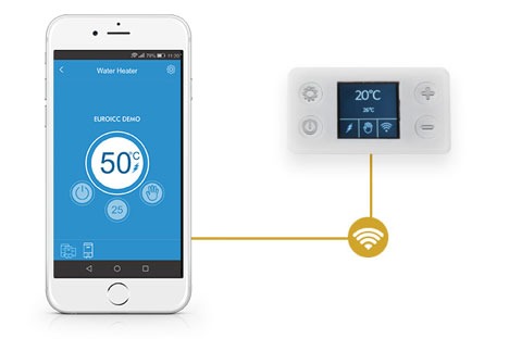
EST-100 smart thermostat for electric storage water heaters, introduced by Euroicc, combines reliable mechanics and high-tech electronics in a single device. It’s a rod or stem type electronic thermostat with smart control, LCD display and Wi-Fi module that can be controlled via Android and iOS mobile apps.
[1] https://eur-lex.europa.eu/legal-content/EN/TXT/HTML/?uri=CELEX:32013R0812#ntr1-L_2013239EN.01008301-E0001
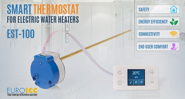
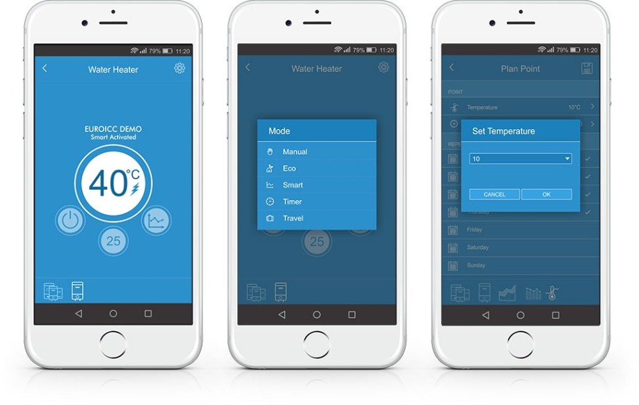
EST-100 solution consists of 2 elements, connected by a quick faston connection cable. The first element is the electromechanical thermostat, which controls the heater and collects data about water temperature. The second element is electronics with LCD TFT display 1.44'', 4 buttons, user interface, and Wi-Fi module. Mobile applications, as a part of EST-100 solution, provide complete product functionality and enable remote control of the electric storage water heater. The water heaters’ end-user is provided with 5 selectable operating modes and 2 background operating functions.
Is rod or stem type of thermostats the only one?
Some of the electric storage water heaters use the different type of thermostats, mostly the capillary version. The capillary solution usually consists of two units, where the first is a functional one, and the another is a safety thermostat. There are also solutions where one device comprises both kinds of thermostats.
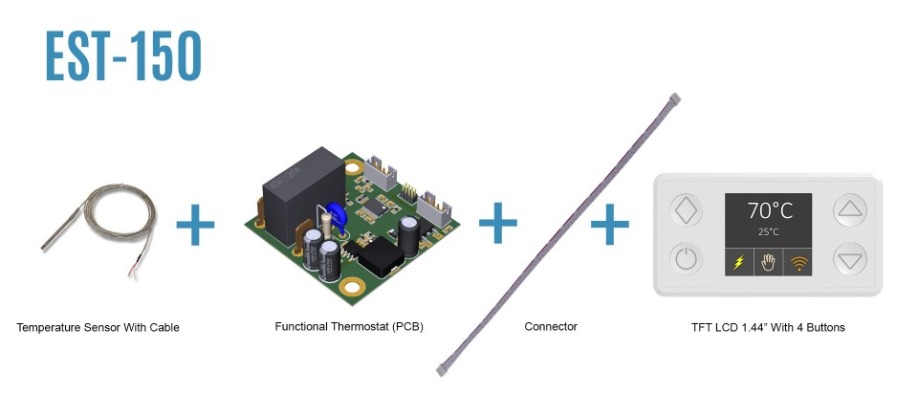
In order to fulfill the needs of DWH manufacturers who use the conventional capillary thermostats, Euroicc is developing capillary smart thermostat product version. This solution is called EST-150 smart thermostat. The PCB is replacing the functional thermostat and the conventional mechanical safety thermostat should be kept in the water heater as an integral part of the solution. Instead of being placed in the stem, the two temperature sensors are located on the cable. Besides the safety component, this is the only difference between the EST-100 rod and EST-150 capillary solution.
What are the core values of the smart water heater concept?
Every smart water heater has to be safe, energy efficient, connected and to provide exceptional comfort to its users. These are the core values and principles of the Euroicc’s smart thermostats, which are used in the development and manufacturing process.
How can smart thermostat increase the water heater’s safety?
Water heater’s safety is increased and provided by a bimetal disc, bipolar safety cut-out, and safety software. The safety software is responsible for electronic functional cut-off and bimetallic disc for safety cut-out. Euroicc has combined the new technology with traditional mechanical safety. This is considered to be the optimal solution since there are at least two levels of safety - if the electronics and safety software fail, the bimetal disc will cut-out the electrical supply of the heater. In every moment, thanks to the mobile application, the user has remote and complete control over the water heater.

The bipolar safety cut-out is very important since it disconnects all supply conductors, live and neutral, by a single initiating action. The bimetal disc and bipolar safety are well-known and proven in the decades of DWH practice. What sets apart the electronic solutions, like EST-100 and EST-150, is the software. The advanced software is constantly monitoring the water temperature for the user’s additional safety. Two active temperature sensors in thermostat’s rod are vouching for accurate temperature measurement. The thermal hysteresis loop of EST-100 and EST-150 is 4 ± 2°C /39.2 ± 35.6 °F. It can be even narrower, but the detailed laboratory tests have shown that this is the optimal tradeoff between the accuracy and relay durability.
Why is accurate and constant temperature measurement so important?
Besides the obvious answer - to prevent the possible overheating, there are less known but also important safety aspects. The first one is Anti-Legionella and the second is freeze protection function. Even the smart function and smart control would be impossible without the precise temperature measurement data.
When the water temperature doesn’t reach a higher level of degrees, for a longer period of time (i.e. 70 °C/158 °F, 2 weeks in a row), the dangerous and harmful bacteria (Legionella) can flourish. If neglected, this process can be a threat to the user's health. This is why the smart thermostat will automatically activate the Anti-Legionella cycle if the heater does not reach 71 °C/159.8 °F for 15 days in a row. In Anti-Legionella cycle, the water is heated to 75 °C/167 °F for 15 minutes and this treatment will remove all potentially harmful bacteria from the water.
Another part of the safety software, constantly operating in the background, is the freeze protection function. The smart thermostat prevents water temperature to drop below 10 °C/50 °F. If the temperature falls below this level, the heater will turn on automatically and heat the water to 15 °C/59 °F. The water temperature is constantly kept at 10 °C/50 °F, in order to prevent freezing in winter periods. If there is a risk of frost, the water heater must be drained ahead of the cold season in case the appliance will not be used for several days or if the power supply is disconnected.
How can smart thermostat increase the energy efficiency?
The electronic temperature measurement with two temperature sensors guarantees the accurate water heater operation. This is fundamental for energy saving modes and smart thermostat functionalities. EST-100 and EST-150 smart thermostats have 3 energy saving modes: Eco, Timer and Smart.
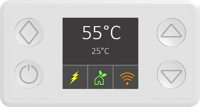
In Eco mode, the water temperature is kept at 55 °C/131° F. This temperature level enables optimal long-term water heater operation, in terms of energy savings, lower heat losses, hot water availability and heating element durability. This mode is recommended for traditional usage when the water heater is left to operate continuously at one set point.
Timer programmable mode, allows the users to program the water heater in line with their needs. Water temperature can be set hourly, daily and weekly and saved as a personalized plan. The programming is done via a mobile application. The major energy savings can be made by programming the water heater to operate only when really needed and in off-peak hours.
Smart mode activates the advanced software for heating optimization, reducing energy consumption by up to 15%. The smart function enables the water heater to learn shower habits and to adjust water heating to its user’s needs. This means that hot water is available when needed, but made with major energy savings. The European Commission demands at least 7% of energy savings to be gained due to smart control, under the prescribed conditions[1]. If prescribed conditions and smart control factor are fulfilled, the electric storage water heater is ‘’smart control compliant’’.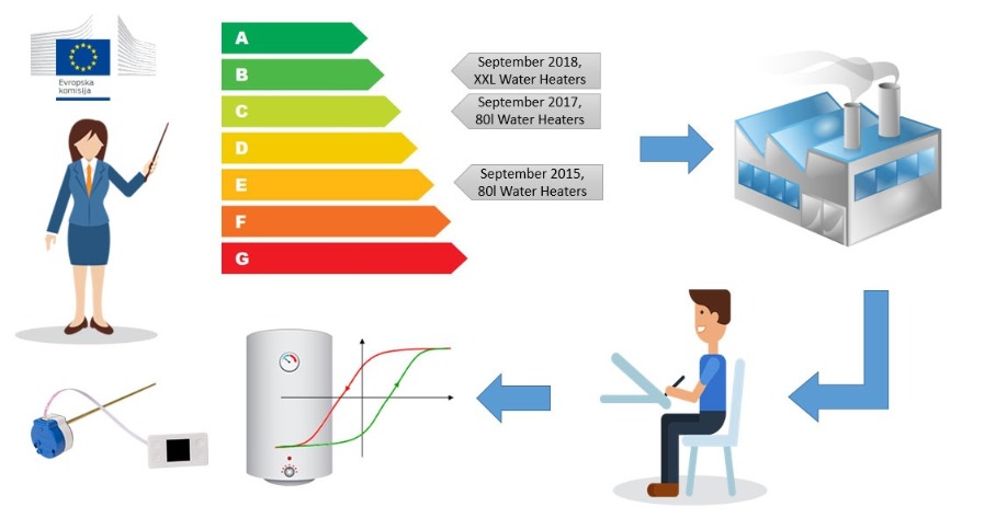
How can water heater become a smart home device?
Any electric storage water heater with EST-100 or EST-150 smart thermostat automatically becomes a smart home device. Integrated Wi-Fi module enables a wireless connection of the water heater. The remote control is provided via easy-to-use Android and iOS apps. With a cloud solution, the water heater can be connected and controlled via the internet too, providing the real Internet of Things (IoT) experience and benefits. Remote control from any location is perceived to be a major innovation in the HVAC industry and the highest added value for the end-user.
How can smart water heater provide maximum comfort to its users?
The
recent water heater industry trend is digital control with
user-friendly HMI. One of the main features of
EST-100 and EST-150 is an advanced
color LCD display with 4 buttons for easy settings and water heater control.
It’s important to create the innovations which are simple, intuitive and easy
for everyday usage. Euroicc’s in-house research
has shown that displays with more than 4
buttons are too complicated for the average
user. In order to provide flexibility and customization options, the buttons
and display plastics can be UV printed with different logos and icons.
Even though the displays are currently the cutting edge solutions, the future belongs to the remote control and intuitive Android and iOS mobile applications. Mobile apps provide a unique water heater user experience and add a new dimension of comfortable usage. You can turn on the water heater before leaving the office, and hot shower water will be waiting for you at home. With the branded mobile apps, DWH manufacturers can stand out from the competition and increase their brand awareness. Language localization in mobile apps is also really appreciated and popular among the users.
By implementing the Artificial Intelligence (AI) concept in its products, DWH manufacturers can create added value for the users. When the smart mode is activated, the software is 2 weeks collecting data about the water temperature acquired from the temperature sensors. The collected data is being processed and applied afterward in the heating process. The heating process is being optimized according to the user’s needs. Basically, the water heater is ‘’learning’’ its users' shower routine and implementing it later on in its operation.

Conclusion
It's fascinating how technology changes our businesses and our lives. The new concepts like Artificial Intelligence (AI) and the Internet of Things (IoT) will shape the industries and be one of the most important growth drivers. Innovations, quick adaptation and creation of added and unique value to the user are the best ways to distinguish ourselves from the competition. The smart thermostats are changing the HVAC industry, especially the water heating segment. The only question is: are we ready to change?

About the Author
Lazar Ćurčija MSc is a Product Manager for Smart Thermostats in Euroicc. Euroicc is a high-tech electronics company, with in-house development and manufacturing. Euroicc has more than 20 years of experience in building automation, PLCs, microcontrollers and smart home devices. We can help water heater manufacturers in the creation of smart, energy efficient and connected products and solutions.

Thomas Brand from Analog Devices explains the demands on sensors for future servicing
Improving condition monitoring and diagnostics, as well as overall system optimization, are some of today’s core challenges in the use of mechanical facilities and technical systems. This topic is taking on an ever-greater role not only in the industrial sector, but wherever machines are used. Machines used to be serviced according to a plan, and late maintenance would mean a risk of production downtime. Today, process data from the machines is used for predicting the remaining service life. Especially critical parameters such as temperature, noise, and vibration are recorded to help determine the optimal operating state or even necessary maintenance times. This allows unnecessary wear to be avoided and possible faults and their causes to be detected early on. With the help of this monitoring, considerable optimization potential in terms of facility availability and effectiveness arises, bringing with it decisive advantages. For example, with it, ABB1 could verifiably reduce downtimes by up to 70%, extend motor service life by up to 30%, and decrease the energy consumption of its facilities by up to 10% within a year.
The main element in this predictive maintenance (PM), as it is known in technical jargon, is condition-based monitoring (CBM), usually of rotating machines such as turbines, fans, pumps, and motors. With CBM, information about the operating state is recorded in real time. However, predictions about possible failure or wear are not made. They only come about through PM and thus mark a turning point: With the help of ever-smarter sensors and more powerful communications networks and computing platforms, it is possible to create models, detect changes, and perform detailed calculations on service life.
To create meaningful models, it is necessary to analyze vibrations, temperatures, currents, and magnetic fields. Modern wired and wireless communications methods already permit factory- or company-wide monitoring of facilities today. Additional analysis possibilities are yielded through cloud-based systems so that the data providing information about the condition of the machine can be made accessible to operators and service technicians in a simple way. However, local smart sensors and communications infrastructure on the machines are indispensable as a basis for all of these additional analysis possibilities. How these sensors should look, which requirements are imposed on them, and what the key characteristics are—these and other questions will be considered in this article.
Probably the most fundamental question in condition monitoring is: How long can I let the machine run before maintenance becomes necessary?
In general, it logically applies that the sooner maintenance is performed, the better. However, for the goal of optimizing operating and maintenance costs or to fully achieve maximum facility effectiveness, the knowledge of experts who are familiar with the properties of the machines is needed. In the analysis of motors, these experts predominantly come from the area of bearings/lubrication, which experience has shown to be the weakest link. The experts ultimately decide if a deviation from the normal state with respect to the actual life cycle (see Figure 1) should already lead to repair or even replacement.
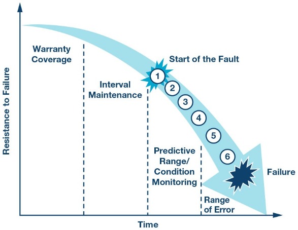
Figure 1. Life cycle of a machine.
Thus, the still unused machine is initially in the so-called warranty phase. Failure at this early stage in the life cycle may not be able to be ruled out, but it is relatively rare and can usually be traced back to production faults. Only in the subsequent phase of interval maintenance do targeted interventions by appropriately trained service personnel begin. They include routine maintenance performed independently of a machine’s condition at specified times or after specified periods of use, as is the case, for example, with an oil change. The probability of failure between the intervals is still very low here, too. With increasing machine age, the condition monitoring phase is reached. From this point on, faults should be expected. Figure 1 shows the following six changes, starting with changed levels in the ultrasonic range (1) and followed by vibrations (2). Through analysis of the lubricant (3) or through a slight increase in temperature (4), the first signs of pending failure can be detected before an actual fault occurs in the form of perceivable noise (5) or heat generation (6). Vibration is often used to identify aging. The vibration patterns of three identical machines over their life cycles are shown in Figure 2. In the initial period, all are within the normal range. However, starting at middle age, the vibrations increase more or less rapidly according to the load before increasing exponentially to the critical range at the end of life. As soon as the machines reach the critical range, an immediate reaction is necessary.
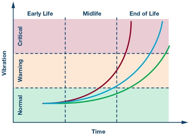
Figure 2. Changes in vibration parameters over time.
Parameters such as the output speed, the gear ratio, and the number of bearing elements are of prime relevance for analysis of the machine vibration pattern. Normally, the vibrations caused by the gearbox are perceived in the frequency domain as a multiple of the shaft speed, whereas characteristic frequencies of bearings usually do not represent harmonic components. Vibrations due to turbulence and cavitation are also often detected. They are typically connected with air and/or liquid flows in fans and pumps and hence tend to be considered as random vibrations. They are usually stationary and exhibit no variance in their statistical properties. However, random vibrations can also be cyclostationary and hence have statistical properties. They are generated by the machines and vary periodically, as in an internal combustion engine in which ignition occurs once per cycle in each cylinder.
The sensor orientation also plays a key role. If a primarily linear vibration is measured by a single-axis sensor, the sensor must be adjusted according to the direction of the vibration. There are also multiaxis sensors that can record vibrations in all directions, but single-axis sensors offer lower noise, a higher force measuring range, and a larger bandwidth due to their physical characteristics.
To enable widespread use of vibration sensors for condition monitoring, two factors are of great importance: low cost and small size. Where previously piezoelectric sensors were frequently used, MEMS-based accelerometers are increasingly being used today. They feature higher resolutions, excellent drift and sensitivity characteristics, and a better signal-to-noise ratio, and they enable detection of extremely low frequency vibrations nearly down to the dc range. They also are extremely power saving, which is why they are also ideal for battery-operated wireless monitoring systems. Another advantage over piezosensors is the possibility of integrating entire systems in a single housing (system in package). These so-called SiP solutions are growing to form smart systems through incorporation of additional important functions: analog-to-digital converters, microcontrollers with embedded firmware for application-specific preprocessing, communications protocols, and universal interfaces, while also including diverse protective functions.
Integrated protective functions are important because excessively high forces acting on the sensor element can often result in sensor damage or even destruction. The integrated detection of a possible overrange delivers a warning or deactivates the sensor element in a gyroscope by switching off its internal clock and thus protecting the sensor element. A SiP solution is shown in Figure 3.
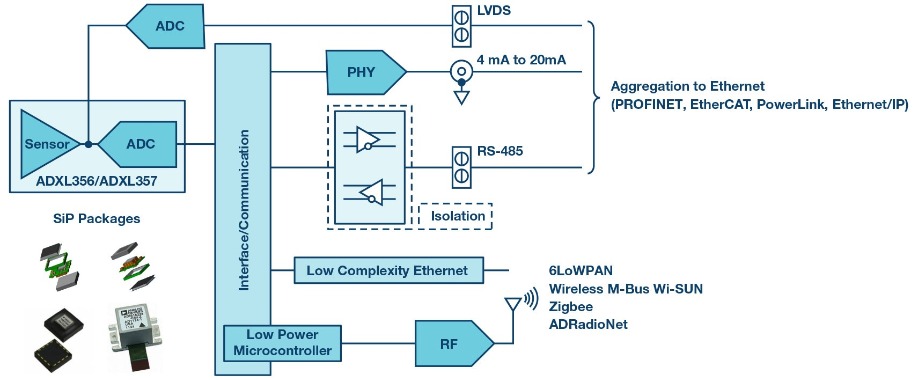
Figure 3. MEMS-based system in package (left side).
As demands in the CBM field increase, so do the demands on the sensors. For useful CBM, the requirements regarding the sensor measuring range (full-scale range, or FSR for short) are already in part greater than ±50 g.
Because the acceleration is proportional to the square of the frequency, these high acceleration forces are reached relatively quickly. This is proven by Equation 1:

Variable a stands for acceleration, f for frequency, and d for the amplitude of vibration. Thus, for example, for a 1 kHz vibration, an amplitude of 1 µm already yields an acceleration of 39.5 g.
Variable a stands for acceleration, f for frequency, and d for the amplitude of vibration. Thus, for example, for a 1 kHz vibration, an amplitude of 1 µm already yields an acceleration of 39.5 g.
Regarding noise performance, this should be very low over as wide a frequency range as possible, from nearly dc to the middle two digit kHz range, so that beyond other artifacts, bearing noise can also already be detected at very low speeds. Yet it is precisely here that the manufacturers of vibration sensors are currently facing a huge challenge, especially for multiaxis sensors. Only a few manufacturers offer adequate low noise sensors with bandwidths of greater than 2 kHz for more than one axis. Analog Devices, Inc. (ADI) has developed the ADXL356/ADXL357 three-axis sensor family especially for CBM applications. It offers very good noise performance and outstanding temperature stability. Despite their limited bandwidth of 1.5 kHz (resonant frequency = 5.5 kHz), these accelerometers still deliver important readings in condition monitoring of lower speed equipment such as wind turbines.
The single-axis sensors in the ADXL100x family are suitable for higher bandwidths. They offer bandwidths of up to 24 kHz (resonant frequency = 45 kHz) and g ranges of up to ± 100 g at an extremely low noise level. Due to the high bandwidth, the majority of faults occurring in rotating machines (damaged plain bearings, imbalance, friction, loosening, gear tooth defects, bearing wear, and cavitation) can be detected with this sensor family.
The analysis of machine states in CBM can be accomplished using various methods. The probably most common methods are analysis in the time domain, analysis in the frequency domain, and a mix of the two.
In vibration analysis in the time domain, the effective value (root mean square, or rms for short), the peak-to-peak value, and the amplitude of vibration are considered (see Figure 4).
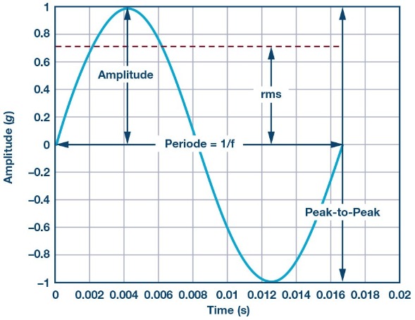
Figure 4. Amplitude, effective value, and peak-to-peak value of a harmonic vibration signal.
The peak-to-peak value reflects the maximum deflection of the motor shaft and thus allows conclusions about its maximum loading to be made. The amplitude value, in contrast, describes the magnitude of the occurring vibration and identifies unusual shock events. However, the duration or the energy during the vibration event and hence the destructive capability are not considered. The effective value is thus usually the most meaningful because it considers both the vibration time history and the vibration amplitude value. A correlation for the statistical threshold for the rms vibration can be obtained through the dependencies of all of these parameters on the motor speed.
This type of analysis proves to be very simple because it requires neither fundamental system knowledge nor any type of spectral analysis.
With frequency-based analysis, the temporally changing vibration signal is decomposed into its frequency components via a fast Fourier transform (FFT). The resulting spectrum plot of magnitude vs. frequency enables monitoring of specific frequency components as well as their harmonics and sidebands, as shown in Figure 5.
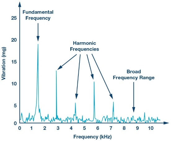
The FFT is a widespread method used in vibration analysis, especially for detecting bearing damage. With it, a corresponding component can be assigned to each frequency component. Through the FFT, the dominant frequency of the repetitive pulses of certain faults caused by contact between rolling elements and defective regions can be filtered out. Due to their different frequency components, different types of bearing damage can be differentiated (damage on outer race, on inner race, or in ball bearing). However, precise information about the bearing, motor, and the complete system is needed for this.
Additionally, the FFT process requires that discrete time blocks of the vibration be repeatedly recorded and processed in a microcontroller. Although this requires slightly more computing power than time-based analysis does, it leads to more detailed analysis of the damage.
The tracking of the fundamental frequency is especially decisive because the effective values and other statistical parameters change with speed. If the statistical parameters change significantly from the last measurement, the fundamental frequency must be checked so that possible false alarms can be avoided.
A change in the respectively measured values over time is common to all three analytical methods. A possible method for monitoring the system can involve first recording the healthy condition, or generating a so-called fingerprint. It is then compared with the constantly recorded data. In the case of excessive deviations or when exceeding the corresponding threshold values, a reaction is necessary. As shown in Figure 6, possible reactions can be warnings (2) or alarms (4). Depending on the severity, the deviations may also require immediate intervention by service personnel.
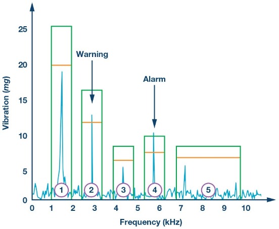
Due to the rapid development of integrated magnetometers, measurement of the stray magnetic field around a motor represents another promising approach to condition monitoring of rotating machines. Measurement is noncontact; that is, no direct connection between the machine and the sensor is required. As with the vibration sensors, with the magnetic field sensors, there are single- and multiaxis versions.
For fault detection, the stray magnetic field should be measured both in the axial direction (parallel to the motor axis) and in the radial direction (at a right angle to the motor shaft). The radial field is usually weakened by the stator core and the motor housing. At the same time, it is significantly affected by the magnetic flux in the air gap. The axial field is generated by the currents in the squirrel-cage rotor and in the end windings of the stator. The position and the orientation of the magnetometer are decisive in enabling measurement of both fields. Hence, selection of a suitable location close to the shaft or the motor housing is recommended. It is also absolutely necessary that the temperature be measured at the same time because the magnetic field strength is directly related to the temperature. Hence, for the most part, today’s magnetic field sensors contain integrated temperature sensors. Calibration of the sensor for compensation of its temperature drift should also not be forgotten.
The FFT is used for magnetic field-based condition monitoring of electric motors just as it was for the vibration measurement case. However, for evaluation of the motor condition, even low frequencies in the range of a few Hz to about 120 Hz are sufficient. The line frequency stands out clearly, whereas the spectrum of low frequency components dominates if a fault is present.
In the case of a broken rotor bar in a squirrel-cage rotor, the slip value also plays a decisive role. It is load-dependent and ideally is 0% at no load. At the rated load, it is between 1% and 5% for healthy machines and increases accordingly in the event of a fault. For CBM, the measurement should hence be performed under the same load conditions to eliminate the effect of load dependency.
Regardless of the type of condition monitoring, even with the most intelligent monitoring concepts, there is no 100% guarantee that there will be no unplanned downtimes, faults, or safety risks. These risks can merely be reduced. However, more and more, PM is crystallizing into a key topic in industry. It is being viewed as a clear prerequisite for the future sustainable success of production facilities. However, for this, innovative and rapid developments—the technologies of which must still be identified in part—are required. Deficits primarily exist in the comparison of customer benefit and cost.
Nevertheless, many industrial firms have recognized the importance of PM as a success factor and hence an opportunity for future business—and not just in the servicing area. The technical feasibility of PM is largely given, despite the extreme challenges, particularly in the field of data analytics. However, PM is currently being driven quite opportunistically. It is expected that future business models will mainly be determined by software components and the value added share of hardware will successively decrease. In conclusion, investments in hardware and software for PM are already worthwhile today in light of the higher yields resulting from longer machine running times.
1 “ABB Ability Smart Sensor jetzt für den europäischen Markt verfügbar”. ABB, April 2017.
Thomas Brand began his career at Analog Devices, Inc., in Munich in October 2015 as part of his master’s thesis. From May 2016 to January 2017, he was part of a trainee program for field application engineers at Analog Devices. Afterward, in February 2017, he moved into the role as field applications engineer. Within this role, he is mainly responsible for large industrial customers. Furthermore, he specializes in the subject area of industrial Ethernet and supports-related matters in Central Europe.
He studied electrical engineering at the University of Cooperative Education in Mosbach before completing his postgraduate studies in International Sales with a master’s degree at the University of Applied Sciences in Constance. He can be reached at thomas.brand@analog.com.
Artificial intelligence (AI) is presently revolutionizing many diverse aspects of our society. For example, by combining the advancements in data mining and deep learning, it is now feasible to utilize AI to analyze large chunks of data from various sources, to identify patterns, provide interactive insights and make intelligent predictions. Kaustubh Gandhi, Product Manager Software, Bosch Sensortec discusses.
One example of this innovative development is applying AI to sensor-generated data, and specifically to data gathered from smartphones and other consumer devices. Motion sensor data, together with other information such as GPS location, provides massive and diverse datasets. Therefore, the question is: "How can the power of AI be leveraged to take full advantage of these synergies?"
Motion data analysis
An illustrative real-world application would be to analyze usage data to determine what a smartphone user is doing at any given moment: sitting, walking, running or sleeping?
In this case, the benefits for a smart product are self-evident:
The heightened interest of smartphone manufacturers in these AI-enabled functions has clearly highlighted the importance of recognizing simple activities such as steps, which are certain to lead to more in-depth analysis of, for example, sports activities. With popular sports such as football, product designers will not focus solely on the athletes themselves, but provide benefits to coaches, fans, and even large corporations such as broadcasters and sportswear designers who will profit from the deep level of insight that can accurately quantify, improve and predict sports performance.
Data acquisition and preprocessing
Having identified the business opportunity, the next logical step is to consider how these massive datasets can be effectively acquired.
In the activity tracking example, the required raw data is collected by means of axial motion sensors, e.g. accelerometers and gyroscopes, which are installed in smartphones, wearables and other portable devices. The motion data is acquired along the three axes (x, y, z) in an entirely unobtrusive way, i.e. movements are continuously tracked and evaluated in a very user-friendly manner.
Training the model
For supervised learning approaches to AI, labeled data is required for training a 'model', so that the classification engine can use this model to classify actual user behavior. For example, we can gather motion data from test users that we know are running or walking, and provide the information to the model to help it learn.
Since this is basically a one-time method, this user 'labeling' task can be performed with very simple apps and camera systems. Our experience indicates that the human error rate in labeling tends to decline with increasing numbers of samples collected. Hence, it makes more sense to take a larger number of sample sets from a limited number of users than to take smaller sample sets from more users.
Getting the raw sensor data alone is not enough. We have observed that to achieve highly accurate classification, certain features need to be carefully defined, i.e. the system needs to be told what features or activities are important for distinguishing individual sequences from one another. The artificial learning process is iterative, and during the preprocessing stage, it is not yet evident which features will be of most relevance. Thus, the device must make certain guesstimates based on domain knowledge of the kind of information that may have an impact on classification accuracy.
For activity recognition purposes, an indicative feature could comprise of 'filtered signals', for example body acceleration (raw acceleration data from a sensor), or 'derived signals' such as Fast Fourier Transform (FFT) values or standard deviation calculations.
For example, a dataset created by UC Irvine Machine Learning Repository (UCI) defines 561 features, based on a group of 30 volunteers who performed six basic activities: standing, sitting, lying down, walking, walking downstairs and walking upstairs.
Pattern recognition and classification
Once the raw motion data is gathered, we need to apply a machine learning technique to classify and analyze it. The available machine learning options are numerous, ranging from logistic regression to neural networks.
One such learning model utilized for AI is 'Support Vector Machines' (SVMs). Physical activities such as walking comprise of a sequence of movements, and since SVMs happen to be excellent for the classification of sequences, they are a logical choice for activity classification.
An SVM is simple to use, to train, scale, and predict, so it is easy to set up multiple sample collection experiments side by side, for use in non-linear classification to handle complex real-life datasets. SVM also enables a wide range of size and performance optimization opportunities.
Having chosen a technique, we must then select a software library for the SVMs. The open source library LibSVM is an excellent choice since it is stable and well documented, supports multi-class classification, and offers extensions for all the major development platforms – from MATLAB to Android.
Challenges of always-on classification
In practice, live classification is required to perform activity recognition during product use, while the user is moving. To keep product costs to a minimum, we need to work out how to balance the costs of transmission, storage and processing, without compromising on the outcome, i.e. the quality of information.
Assuming affordable data transmission, all the data can be stored and processed on the cloud. In reality, this risks a huge data bill for the user and, of course, with the user’s device now requiring an internet connection, an unavoidable Wi-Fi, Bluetooth or 4G module would further drive up the device costs.
To make matters worse, access to even 3G networks in non-urban areas can often be challenging, i.e. when hiking, cycling or swimming. This inherent reliance on substantial data transmissions to the cloud would slowdown updates, necessitate periodic syncing, thus effectively negating the actual benefits of AI motion analysis. Conversely, handling all these operations solely on the device's main processor would clearly result in substantial power draw and reduced execution cycles for other applications. Likewise, storing all data on the device itself would increase storage costs.
Squaring the circle
To resolve these seemingly conflicting factors, we can follow four principles:
By decoupling feature processing from the execution of the classification engine, the processor linked to the acceleration and gyroscope sensors can be far smaller. This effectively eliminates the need for continuous transmission of live data chunks to a more powerful processor. Processing features such as a FFT for transforming time domain signals to frequency domain signals would necessitate a low power fuser core for executing floating-point operations.
Furthermore, in the real world, individual sensors have physical limitations, and their output drifts over time, for example, due to offsets and non-linear scaling caused by soldering and temperature effects. To compensate for such irregularities, sensor fusion is required, and calibration needs to be fast, inline and automatic.

Figure 1: Functional process for activity classification (Source: Bosch Sensortec)
Additionally, the selected data capture rate can significantly affect the amount of computation and transmission required. Typically, a 50 Hz sample rate is sufficient for normal human activities. However, when analyzing the performance of fast moving activities or sports, a sample rate of 200 Hz may be required. Similarly, for faster response times, a separate accelerometer running at 2 kHz may be installed to determine the user’s intent.
To meet these challenges head on, a low-power or application-specific sensor hub can significantly reduce the CPU cycles needed by the classification engine. Examples of such sensor hubs include Bosch Sensortec’s BHI160 and BNO055. The associated software can directly generate fused sensor outputs at varied sensor data rates, and support feature processing.
-7dok27.jpg)
| Figure 2: Smart sensor hub BHI160: low-power smart-hub for activity recognition, specifically designed to enable always-on motion sensing. (Source: Bosch Sensortec) |
-uk0kut.jpg)
| Figure 3: Application specific sensor node BNO055: intelligent 9-axis Absolute Orientation Sensor, combining sensors and sensor fusion in a single package. (Source: Bosch Sensortec) |
The initial choice of the features that will be processed, subsequently greatly impacts the size of the trained model, data volume, and the computational power required for both training and executing inline prediction. Hence, the choice of features sufficient for classifying and differentiating a particular activity is a key decision, and is likely to be a significant commercial differentiator.
Reflecting on the earlier UCI example of a full dataset of activities with 561 features, a model trained with the default LibSVM kernel achieved a test accuracy of activity classification of 91.84 %. However, after completing the training and ranking the features, selecting the most important 19 features was sufficient for achieving a test accuracy of activity classification of 85.38 %. Upon closer examination of the rankings, we found that the most relevant features are frequency domain transformations, and the mean, maximum and minimum of sliding window acceleration raw data. Interestingly, none of these features would have been possible with just preprocessing, i.e. sensor fusion was necessary for this data to be sufficiently reliable and, thus, useful for classification.
Conclusion
In summary, technology has advanced to the point where it is now practical to run advanced AI on portable devices to analyze data from motion sensors. These modern sensors operate at low power, with sensor fusion and software partitioning significantly increasing the efficiency and viability of the overall system, while also greatly simplifying application development.
To add to this sensor infrastructure, we can take advantage of open source libraries and best practice to optimize feature extraction and classification.
It is now quite realistic to offer a truly personalized user experience, leveraging AI to provide sophisticated insights based on data gathered by the sensors in smartphones, wearables and other portable devices. The next few years should bring to light a whole array of as yet unimaginable devices and solutions. AI and sensors are set to open up a new world of exciting opportunities to both designers and end users.
-4jrysz.jpg)
Figure 4: AI and sensors are set to open up a new world of exciting opportunities to both designers and end users. (Source: Bosch; Picture: Depositphotos/Krisdog)
Sources : UCI http://archive.ics.uci.edu/ml/datasets/Smartphone-Based+Recognition+of+Human+Activities+and+Postural+Transitions
About Bosch Sensortec
Bosch Sensortec GmbH is a fully owned subsidiary of Robert Bosch GmbH that develops and markets a wide portfolio of MEMS sensors and solutions tailored for smartphones, tablets, wearable devices and IoT (Internet of Things) applications.

It is widely accepted that simulation will form part of the testing and validation process for autonomous vehicles, but this presents a number of challenges for the simulation tools that could be used for this. Mike Dempsey, Managing Director of Claytex explains
It is now well accepted that simulation will have to form part of the validation process for any autonomous vehicle. This is based on the fact that it is simply not physically possible or practical to conduct all the required tests in the real world due to the sheer number of scenarios that need to be considered.
The RAND Corporation published a report in 2016 that looked into the problem of how many miles an autonomous vehicle would have to be driven to prove it was safer than human operated vehicles. They produced the figure of 5 billion miles as the distance an autonomous vehicle would need to be driven in the real world to have 95% confidence that it was significantly safer than a human driver. “To drive this distance is not feasible especially when you consider that this would have to be repeated every time a line of code or piece of hardware is changed,” says Mike Dempsey, Managing Director of Claytex.
The generally accepted approach, and the route that Claytex advocates, is the need to have a mix of field testing, proving ground testing and simulation to build up the validation process for an autonomous vehicle. The field trials allow the vehicle to be tested in the real world with all the random and unpredictable features and behaviours that exist on the roads today. “Proving ground testing allows us to control many of the scenarios and situations we expose the vehicle to so that we can start to objectively measure its behaviour. However, in both field tests and proving ground tests, there is little chance that you can exactly repeat a scenario and you have no control of environmental factors such as temperature, rain, and more,” Dempsey explains.
“Therefore, it is necessary to use virtual testing in combination with physical tests to allow the rapid and repeatable testing of the autonomous vehicle throughout the development and validation phases. However, in order to rely on virtual testing, it is important to be able to confirm that the simulation produces the same results as the real tests”.
“He continues: “The simulation tools used need to be able to accurately recreate real-world locations so that we can build exactly the same scenarios we experience in the field in simulation. This means the simulation tool needs to be able to include traffic, pedestrians, cyclists and many other movable objects that might feature in the recorded scenarios. We also need our simulation tool to support running in real-time with the unmodified vehicle control system so that we are testing the same controller that runs in the vehicle”.

Driving in Montreal with complex scenarios including traffic, pedestrians and cyclists
“This is the challenge that we are working on at Claytex. We want to ensure that virtual testing is truly representative, and that the AV will respond the same on the road as it did in simulation. Just as a driving simulator must immerse the driver in a convincing virtual reality, the sensor models used to test an AV must accurately reproduce the signals communicated by real sensors in real situations,” Dempsey comments.
Claytex is an established distributor and systems integrator of the 3D driving simulation software rFpro. The software provides high quality graphics and accurate 3D models of real-world locations.
Using rFpro as the core simulation environment enables Claytex to build full autonomous vehicle simulators that allow the vehicle control system to be immersed into the virtual test environment. rFpro renders images using physical modelling techniques, the laws of physics, rather than the computationally efficient special effects developed for the gaming and film industries. This means that rFpro images don't just convince human viewers, they are also suitable for use with machine vision systems that must be fed sensor data that correlates closely with the real-world.
New sensor models help autonomous cars to ‘see’ the road ahead more clearly
Dempsey explains that one of the key challenges of building a virtual testing environment for autonomous vehicles is the need to replace the sensors that the vehicle control system relies on with sensor models. “These sensor models need to generate the same output format messages as the real device and they must replicate how the real device perceives the environment. For a camera, this is relatively easy because rFpro already generates very high-quality images and it is capable of doing that at resolutions and frame rates that exceed those being used in autonomous vehicles today.”
He argues that it is the LiDAR, radar and numerous other sensors that need the most work. “rFpro has developed solutions for a number of the technical limitations that have constrained sensor modelling until now, including new approaches to rendering, beam divergence, sensor motion and camera lens distortion.”
“In order to create a representative model of a LiDAR sensor a sensor model is needed that captures the behaviour of the real device,” adds Dempsey. “So, if the real device is a scanning LiDAR and spins at 1200 rpm, then the sensor model needs to do the same and whilst it’s spinning it needs to move through the virtual world. The model needs to measure the distance and intensity of the reflection to each point in the environment and pack this into the same UDP message format used by the real sensor”. This is all possible using rFpro and the VeSyMA – Autonomous SDK developed by Claytex.
The VeSyMA – Autonomous SDK (Sensor Development Kit) has been created to make the creation of device specific sensor models easy by encapsulating a lot of the common features needed by sensor models. Using the SDK, Claytex have created a suite of generic sensors (radar, LiDAR, camera, ultrasound and GPS) that can be used in the early stages of an autonomous vehicle development project to assess what kind of sensing is desirable.
In addition, Claytex are building a library of device specific sensor models that support testing throughout the development process. The first of these device specific models are already being used to support the virtual testing of an autonomous vehicle and the range of sensors available will be continuously added to.
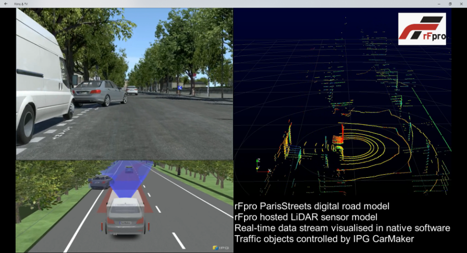
Driving in Paris with a LiDAR sensor model hosted in rFpro providing data to sensor suppliers own data visualisation tool
With sensor models representative of the real devices in place, the focus then shifts to the virtual world and the definition of the test scenarios. rFpro are able to provide a wide range of high-fidelity models of public roads, proving grounds and race tracks. These models are all built from detailed surveys of the real locations and cover locations such as Paris, rural Warwickshire, Connecticut, Shanghai and many other world locations.
“Support for traffic, pedestrians and cyclists as well as other movable objects in the virtual world enable us to create a wide variety of test scenarios that we can then repeat under different weather and lighting conditions. These capabilities allow us to start building complex scenarios that we can use to test the vehicle control system and measure its performance”, concludes Mike Dempsey, Managing Director of Claytex.
The drive towards autonomy is continuing to push the development of virtual test environments into new and challenging areas. The challenge of producing physics based sensor models that can run in real-time is one being tackled by Claytex with the first full vehicle simulators now in operation.
Mike is the Managing Director of Claytex and a technical expert in modelling and simulation using Modelica and FMI. Mike studied Automotive Engineering at Loughborough University and then worked at Ford and Rover on powertrain simulation. After starting Claytex as a consultancy, the company has grown and also become a specialist partner for Dassault Systems, training provider and simulation tool developer. Claytex now works with Formula 1 and NASCAR teams as well as Automotive OEM’s to deliver models and tools covering many different applications helping to create next generation of products.

With the growth of new applications, there is a rapidly increasing demand for new and more sophisticated sensors. Nicolas Sauvage, Sr. Director Ecosystem at InvenSense explains why.
The increasing variety of applications for the Internet of Things (IoT) and Industrial Internet of Things (IIoT) and their growing adoption, are driving predictions that the sales volume for sensors will reach 75 billion units by 2025. It would be fair to assume sensors will eventually become commodity components. As machine learning grows in importance, these increasing numbers of sensors will need to be more intelligent and capable. Use-cases unforeseen just five years ago are driving the development of sensors with unprecedented performance.
A growing number of applications have emerged in consumer markets. With imaging, for example, consumers are now looking for a level of photo quality in slim smartphones that had earlier only been possible with expensive and bulky DSLR cameras — and this while walking, if not running. To achieve such image quality, with the limited optics that can be accommodated in such a tight space, OEMs have deployed Optical Image Stabilization (OIS) and Electronic Image Stabilization (EIS) solutions. The performance of the OIS/EIS components, especially the motion sensor, has a major impact on overall performance. For example, the Google Pixel 3 device, which has a camera with both OIS and EIS, received a DXO Mark score of over 100 from DxOMark Image Labs, never given to a smartphone until 2018. The technology that led to the high performance is a motion tracking sensor that has extremely low gyroscope and accelerometer noise (<0.004 dps/√Hz and <100µg/√HZ respectively) and sensitivity error within 0.5%, while having very high temperature stability (within ±0.016%/◦C maximum) given the fast temperature change constraints.
It is not just cameras that require such precise motion sensor performance. Virtual reality (VR), augmented reality (AR), and mixed reality (XR) all need low noise and extremely good temperature stability.
Dead-reckoning systems are used for navigation in both consumer and commercial applications. They provide location data in the absence of GNSS/GPS signals by means of Inertial Measurement Units (IMU), which used linear acceleration information derived from accelerometers and angular rotation rate from gyroscopes to calculate altitude, angular rate. linear velocity, and position. The accuracy of these measurements is critical because errors are additive — they increase over time. For high-precision navigation, a gyroscope needs to have extremely low gyro offset over temperature (between 3 to 5mdps/oC) and gyro noise density (below 4mdps/√Hz).
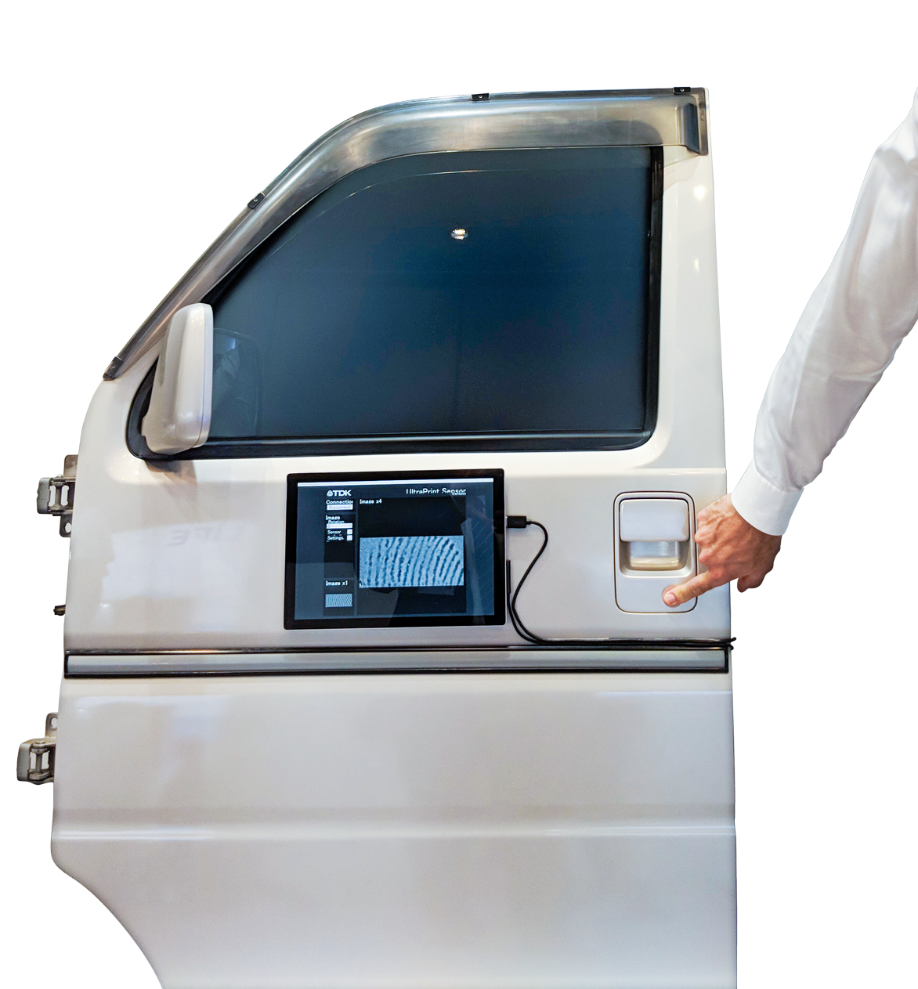
A promising consumer application for dead-reckoning, is to sense one’s location inside a shopping mall. It is particularly challenging to sense the floor someone is on. It would allow users to know which shops are near them. More importantly, it could save time and lives by providing emergency services with the specific floor and location where the mobile caller requested help, rather than searching floor by floor. This can be achieved with high-precision, low-noise pressure sensors that can measure individual stairs. This is now achievable because pressure sensors are available that can go as low as one Pascal, or about 10 cm in precision.
In many cases, sensor performance is application-driven. For example, drones care more about bias, time, and temperature stability, while house-cleaning robots will care mostly about bias stability and noise. Virtual Reality (VR) stand-alone head mounted devices (HMD) will need exceptionally good temperature linearity and stability, as well low hysteresis and noise to provide the best possible user experience. For the very high precision required by VR and Augmented Reality (AR) controllers, sensors will need to have high resolution to be able to accurately handle the slow and precise movements of a hand.
For the Industrial Internet of Things (IIoT), including the manufacturing, automotive, and aerospace sectors, requirements are generally an order of magnitude more demanding than for consumer applications. For example, inaccuracy for consumer applications can typically be 1000ppm (parts per million) and for automotive and IIoT, 100ppm.
For precise navigation, to take one example, vibration isolation for sensors is extremely important. The extreme vibration experienced by a driverless agricultural tractor can cause navigational errors because of its effects on the motion tracking sensor. To deal with this problem, navigational grade solutions require bias stability of below 2°/hr for gyroscopes and below 10µg on Accelerometer side, while an ARW (angle random walk) of 0.084 °/√hr and VRW (Velocity Random Walk) of 0.016 m/s/√hr. Beyond just sensor performance, it is also important to have very little misalignment errors and mounting errors, less than 0.05° for both.
The good news is that silicon MEMS allow lower cost structures than piezo, with batch processing, and this has opened new markets in low-cost sensing alternatives for these demanding applications.
“Industry 4.0” drives production towards constant and permanent monitoring of a large and increasing number of processing parameters. Sensors are integrated in new production equipment, but they can also be added to older equipment to allow for machine health monitoring. Online monitoring, instead of monthly manual read-out, brings clear benefits and ROI: reduced downtime by as much as 70%; extended motor lifetimes by up to 30%; reduced energy consumptions by up to 10%. Indeed, like a person, it is always better to catch the symptoms early than wait until they get too severe.
Take the example of a sensor’s potential to address more use-cases than ever before by ‘simply’ improving one of its performance metrics by an order of magnitude: the pressure sensor’s noise, measured as Pascal RMS. When you can achieve a pressure noise at the level of one pascal, you are able to detect stair steps of 18cm very easily – and this drives new use cases not possible before. New use cases could include activity monitoring and calories counting, improved flight control for drones, improved interior routes and travel time, rapid emergency response in the right floor of your building and more.
Microphones are also increasingly deployed in our homes, with smart speakers having multiple microphones; for example, the Amazon Echo has seven microphones. You can easily imagine a future where a family has more than 100 microphones inside their home. These devices require very high-performance microphones, with a signal-to-noise-ratio (SNR) of more than 70 dB, while having an acoustic overload point (AOP) of more than 120 dB. A good example is ICS-40730 that provides 74dB SNR and 123dB AOP. This allows the microphone to still listen to everything happening near the smart speaker even in the presence of loud noises, like a door closing too hard, or a TV playing an action movie too close to the smart speaker.
Another category of IoT and IIoT is machines that move, such as self-driving cars, service robots and industrial monitoring drones. For them to be able to “see” their surrounding precisely and avoid obstacles is increasingly important, in addition to cost and size. Range finding or time-of-flight (ToF) sensors are starting to address these applications better and better, with some using ultrasonic methods to measure distances up to five meters very precisely.
Ultrasonic technology also allows new use-cases in industrial or consumer contexts with fingerprint sensors that can work well even under metal or plastic, allowing for more challenging environments to provide secure access via fingerprint. For example, challenges such as security requirements, needing both false acceptance rate (FAR, or giving access to an unauthorized person) of at least one to 50,000 and false rejection rate (FRR, or not giving to the authorized person) of less than two percent, are still met with ultrasonic solutions, and are actually better than traditional solutions for use-cases like people using wet fingers after washing their hands or getting out of the shower.
The examples covered in this article are only a few of many use-cases that require increasing performance from many sensors, on various, and many times different, performance KPIs. Innovation is simply the way forward to address these demanding expectations, and it won’t be long before digital experiences are humanized by sensors across all industries.
Nicolas Sauvage is Sr. Director of Ecosystem at TDK-InvenSense, responsible for corporate development and all strategic ecosystem relationships, including Google and Qualcomm, and other HW/SW/System companies. Nicolas is an alumnus of ISEN, London Business School, INSEAD and Stanford GSB.
-x5q2zr.jpg)
We live in a connected world: It is only a matter of time before hundreds of billions of connected IoT devices and sensors provide mankind with ubiquitous information… or is it really? What is certain is that key issues remain to be solved for these optimistic projections to be realised, and energy supply is one of them: how can these billions or even trillions of devices be powered, sustainably and cost-effectively asks Mathieu Bellanger, CTO of Lightricity?
There are typically three options being considered for powering IoT sensors:
On average, people typically spend 90% of their time indoors. Hence one can also imagine that a considerable fraction of current and future IoT devices are to be located in an indoor environment: homes, offices, supermarkets, factories, warehouses, hospitals, to name a few. However, most of existing light energy harvesting solutions, based on silicon active materials, have been designed principally for outdoor use and show a drastic drop of performance in low-light level indoor environments. Other alternatives based on dye-sensitised solar cells (DSSC) and organic photovoltaics (OPV) offer a small power density increase but are larger in size (tens of cm2) and frequently suffer from material degradation and limited lifetime (a few years only). As a consequence, this means none of the commercially available solutions can provide enough “juice” or power for a wide range of wireless applications (including wearables), where there is a clear limitation in the size of the final device or product. So is this the end of it?
Lightricity Ltd1 is a high-tech company which recently span-out from Sharp Laboratories of Europe, Sharp’s European R&D laboratory. After over 4 years of intense research to develop the perfect indoor solar cell, Lightricity has been set-up in 2017 to further develop and commercialise its unique technology based on an inorganic material. With efficiencies up to 35% achieved under standard artificial lighting conditions (200 lux white LED or Fluorescent/FL light), Lightricity currently offers the world’s most efficient photovoltaic (PV) energy harvesting components (ExCellLight) for IoT devices. This high conversion efficiency enables now up to six times more power to be delivered to a sensor or IoT device (Figure 1), avoiding the multiple replacements of coin cells, AAA-AA types of batteries.
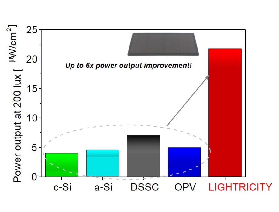
Figure 1: Comparison of indoor Photovoltaic (PV) Energy Harvesting technologies
This power boost can be used to provide more device functionality or to reduce the footprint of the complete system (to a few cm2). For example, Lightricity’s energy harvesting component can provide a perpetual source of energy for more power-hungry air-quality gas sensors, such as CO2 sensors. The Lightricity team, in collaboration with Gas Sensing Solutions (CO2 sensor manufacturer) has previously demonstrated an autonomous wireless CO2, temperature, light, humidity sensor that can perpetually perform and transmit all environmental measurements every 2min 30s at 200 lux, only using a 10 cm2 Lightricity PV cell2. Over 10 years typical product lifetime, up to 150 battery replacements can be avoided, assuming 1000 lux average illumination (e.g. retail environment) - thereby saving €100’s in maintenance and battery costs to the end-users (Figure 2).

Figure 2: Lightricity battery equivalent under indoor conditions
In a project funded by Innovate UK, and in partnership with Ilika (solid-state battery storage) and E-peas (power management chipsets), Lightricity is currently developing a second generation of compact everlasting power supply that can connect to any IoT sensor or wireless tracking devices and beacons (Figure 3).
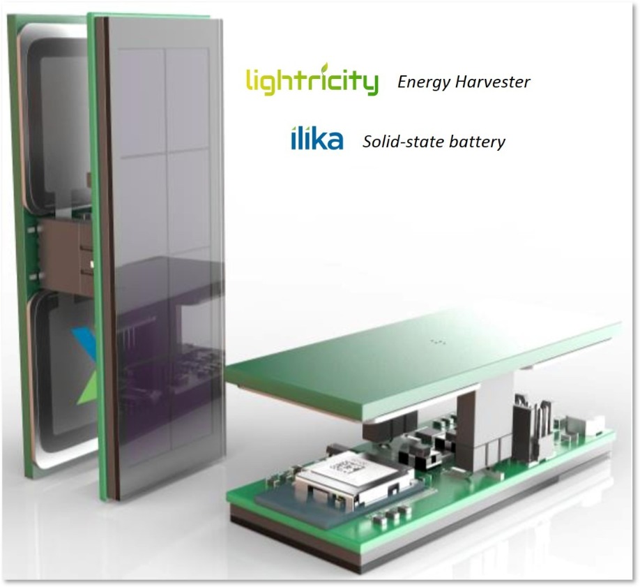
Figure 3: Energy harvesting power pack (Lightricity, Ilika)
Some environments can be particularly harsh: Lightricity’s energy harvesting component has been designed to withstand temperatures of up to 150 °C continuously, and up to 250 °C intermittently. The temperature coefficient of Lightricity’s device is twice better than that of silicon, translating into up to 8x performance improvement at elevated temperatures. This opens new applications in automotive and industrial environments, and also new use cases in health monitoring for worker safety, emergency responder safety and sports applications.
These developments demonstrate that powering IoT devices and sensors by energy harvesting is both practical and beneficial for lowering cost of ownership. This opens the way to large scale deployment of connected IoT devices in the short term.
References:
2 “Development of an Indoor Photovoltaic Energy Harvesting Module for Autonomous Sensors in Building Air Quality Applications”, X. Yue, M. Kauer, M. Bellanger and al. IEEE Internet of Things Journal, Vol. 4, No. 6, December 2017, DOI: 10.1109/JIOT.2017.2754981
Up until now bats have been the advocates of being able to navigate with sound. They rely on echolocation to detect obstacles in flight, forage for food and to “see” in dark caves. Now the Munich-based startup Toposens managed to extract the bat’s trick to navigate and use it to detect people and objects accurately. The company thereby developed the first 3D ultrasound sensor worldwide.
Toposens provides echolocation, i.e. the ability to “see with sound” for the automotive industry and robotics. Up until today, ultrasound has only been used for one-dimensional applications, e.g. precise distance measurement for industrial applications. Toposens invented the first 3D ultrasound sensor system. It can detect multiple objects and people in real-time and generate a 3D point cloud of its near-field environment.

By using the principles of bionics i.e. engineering a reliable product based on biological methods found in nature, many of the sensor’s features are closely related to the echolocation system used by bats. Toposens sensors send out signals, evaluate the echoes that come back and precisely detect where in a given space both static as well as dynamic objects are located in real time.
Even though ultrasound has been studied by scientists for over 200 years, its true capabilities have not yet been unleashed. Ultrasound technology provides many interesting characteristics that have not been combined into any other 3D sensor yet. Toposens’ current sensor TS ALPHA is very robust and can see in the dark, under varying lighting conditions, through dust and dirt and does not have any problems with transparent or reflecting surfaces. It currently operates at the lower end of ultrasound with approximately 40kHz.
To give potential customers the possibility to test the sensor in various applications and under multiple conditions, Toposens launched a Development Kit for testing and prototyping purposes. The latest Development Kit TS ALPHA covers applications in both the robotic as well as the automotive field. To simulate a real-world use case where the sensor evaluates the near field environment during relatively slow, Toposens recently tested the Development Kit in a specific robotics parcours.
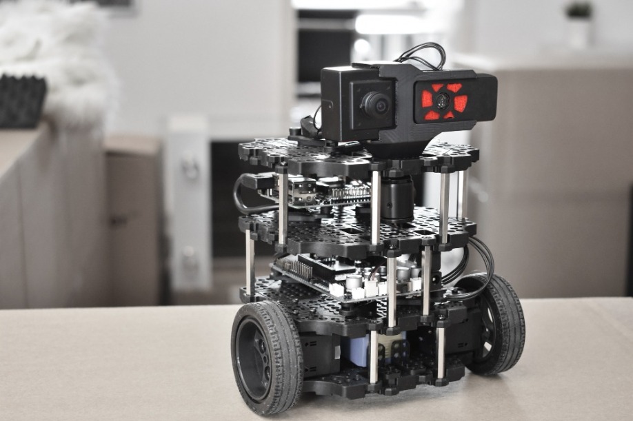
Toposens engineers challenged the sensor unit TS ALPHA by mounting it onto a robot and sending the robot through a parcours consisting of various obstacles located in the close range. Under dimmed light and bad visual conditions, TS ALPHA stepped onto the battlefield. Navigating through the parcours, the sensor - while still in movement - had to detect a transparent bottle and a bowl consisting of very fine grates and fight its way through dynamic obstacles in the form of coworkers reaching out for the sensor.
A pipe of convex shape, fluffy fabric surfaces and a door mat rounded off the parcours for the ultrasound sensor. While TS ALPHA felt at home in his natural habitat and calculated the 3D coordinates of all nearby objects in real time, those same objects would not have been detectable under the same conditions by conventional cameras, radars or LiDAR systems. Due to limited visibility and lighting but also due to the shape and characteristics of the objects like the transparency of the glass bottle or the fine mash of the bowl, the objects would be difficult to detect in the raw data of existing sensor technology. These issues of reflecting and transparent surfaces or bad lighting conditions appear frequently when sensors are being used in the automotive field. Darkness, fog, wind and sun do not interrupt ultrasound, whereas the weather heavily affects cameras and lasers.
As outlined in the parcours experiment, 3D ultrasound technology has strong benefits when it comes to near-field sensing. It covers objects in the opening angle of up to 180° (horizontally and vertically), has a range of up to 5m and generates real time data in the form of clustered data points.
Toposens is using a minimalistic approach with the TS ALPHA Sensor by limiting its size while keeping all of the functionalities at a peak level. Standard hardware components are put together in a special layout and combined with proprietary algorithms, machine vision and AI-software. The hardware components are off-the-shelf. They are very small, use little energy and weigh below 20g. Unique is the ability of the sensor to immediately evaluate the received data on a small built-in microcontroller, making an external control unit obsolete and keeping the generated data flow low. Only for further clustering and processing of the data, additional hardware is needed. The company’s main knowhow lies in the sophisticated algorithms, which turn the ultrasound signals into 3D coordinates.
Besides covering the long distance, a fundamental requirement for autonomous vehicles is to perceive their near-field surroundings as precisely as possible. Toposens sensors provide reliable, rich and three-dimensional data (point cloud) for the close-range environment around the vehicle. The sensors are therefore well suited for applications in the automotive field and are able to cover areas, that conventional radar and camera technologies are struggling with.
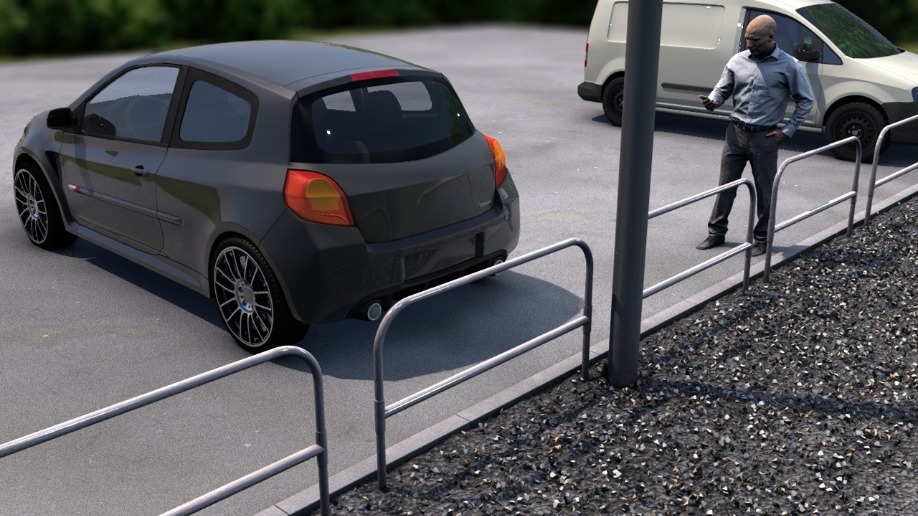
For improved accuracy and safety in everyday parking situations, sensors have become an essential in every car. Up until today, they helped the driver steer more safely and guide him into a parking spot via sound and light signals. Although the currently installed sensors provide a good guideline to avoid collisions, while navigating the car into a tight parking spot, they still leave a lot of room for improvement. Conventional ultrasound sensors used for parking assistance only record one-dimensional data, namely the distance to the closest object. Azimuth and especially elevation angles of objects can hardly be calculated, and vertical opening angles must be limited strictly, so many objects – such as the curb – cannot be detected at all.
As every drive starts from a parking position and ends with a parking maneuver, close-range sensing is one of the crucial challenges in going from L3 to L4 automation. Thinking about autonomous parking and precise manoeuvring in tight parking spaces, distance measurement alone quickly becomes insufficient. In order to take things to the next level, more sophisticated sensors are needed around the car. By ultimately using 3D ultrasound sensors, the car’s surroundings can be evaluated accurately. Furthermore, blind spot monitors are an option that may include more than monitoring the sides of the vehicle. What mainly differentiates the technology from existing parking sensors are both the algorithms and the special layout which allow 3D sensing with commoditized, readily available hardware.
The sensor data is further useful for additional comfort features, e.g. gesture control to open doors and trunks, positioning the vehicle for automated charging (for EVs), collision avoidance for automatically opening doors and many more.
With further improvements in autonomous driving space, the behavior of the driver is also likely to change. While drivers today have to be completely focused on the road, ready to react every millisecond, this could change once cars can steer and break fully automatically. The drivers can lean back and relax, work on their computers, turn to the children in the back seat, or temporarily enjoy an expanded infotainment program.
In this vision of autonomous driving, drivers can use their travel time for activities besides driving. This puts new demands on assistance systems. Just like the numerous sensors available for analyzing a car's external environment, similar knowledge is needed for the interieur in order to realize a more secure and intuitive interaction experience. In this scope of application, the usage of 3D ultrasound provides interesting advantages. Data gained from the 3D ultrasound sensor is able to identify the number of people sitting in the car, their size and their posture. Based on the information regarding where people are sitting and how big they are, airbags could also be adjusted to individual body sizes to further improve safety. Toposens technology does not collect any personal data since ultrasound cannot evaluate visual material. Instead, anonymous point cloud data is recorded. This is an especially important consideration in terms of privacy and data protection. Last but not least, gesture simulation in the interior of the car can be used for information and entertainment purposes, e.g. controlling your car’s infotainment systems with simple gestures.
There is no doubt that future autonomous vehicles need more assistance to operate safely in our everyday lives. Whether you are living in a big city where people detection and accurate parking plays a major role or on the countryside where automated charging can assist you, sensors will have a big impact on your everyday life. Toposens contributes to the high quality of sensor output and keeps developing new products to accelerate the advancements in sensor technology.

Jackie Cannon

Mark Andrews


Sukhi Bhadal


Scott Adams
Scott.Adams@angelbc.com
Alex Mayo
Alex.Mayo@angelbc.com


Sensor Solutions is published four times a year on a controlled circulation basis. All information herein is believed to be correct at time of going to press. The publisher does not accept responsibility for any errors and omissions. The views expressed in this publication are not necessarily those of the publisher. Every effort has been made to obtain copyright permission for the material contained in this publication. Angel Business Communications Ltd will be happy to acknowledge any copyright oversights in a subsequent issue of the publication.
Angel Business Communications Ltd © Copyright 2018. All rights reserved. Contents may not be reproduced in whole or part without the written consent of the publishers.
