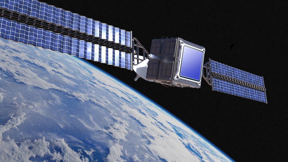
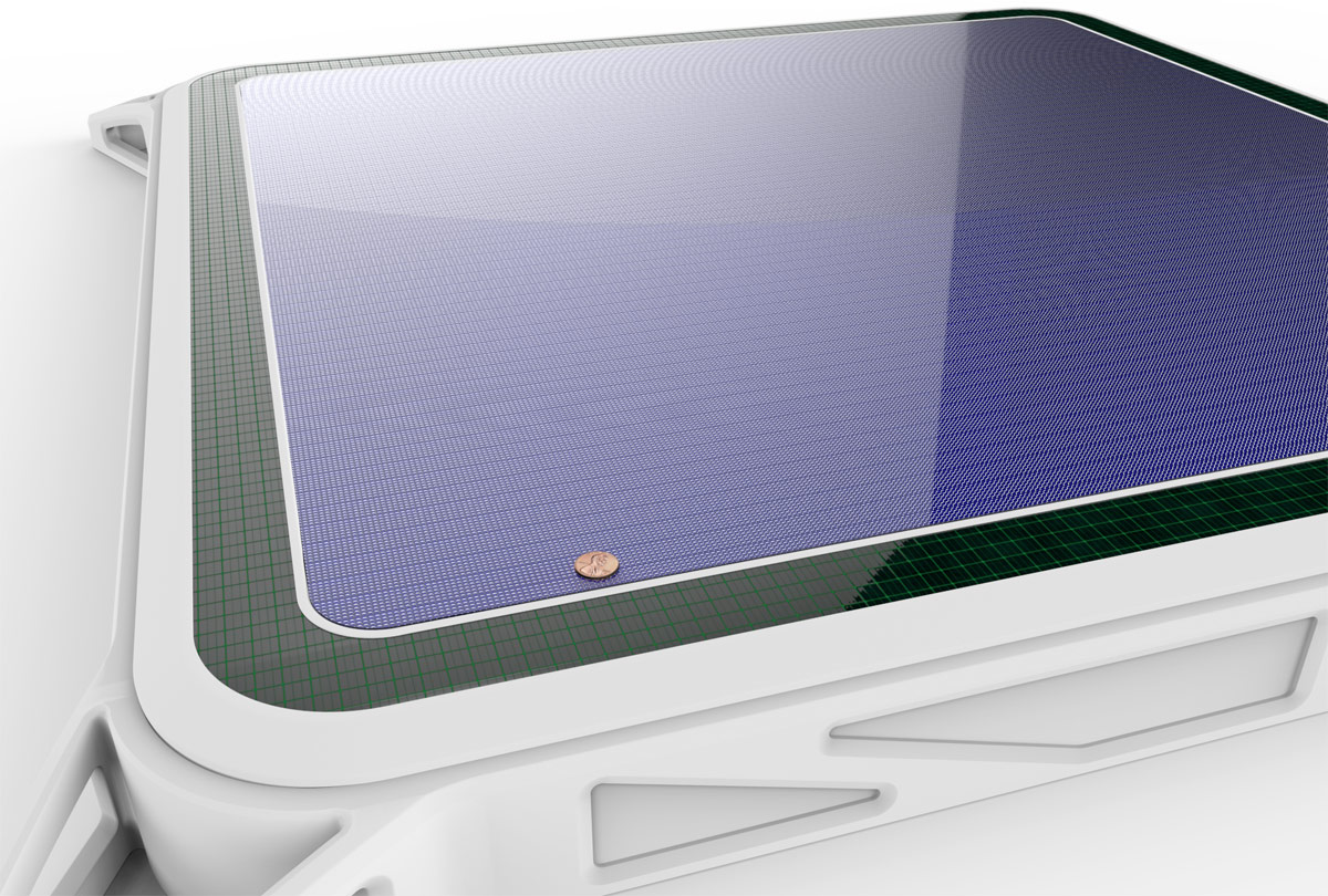
“We’ve been working on a flat antenna which can be fitted on the side of the fuselage, yet is also electronically steerable. The antenna is actually made up of smaller antenna elements connected together to amplify the received signal. The antenna is highly directional, receiving signals that arrive in defined beam.
Designing a high-performance broadband satellite antenna is difficult. International airlines fly all over the world and want the system to work anywhere.
In equatorial regions, the satellite beam is coming down at around 90 degrees. But on high-latitude routes, like the extremely busy North Atlantic routes, the satellite signal beam comes in at a low skew-angle. Conventional flat panel designs have extremely variable performance, especially when flying at high latitudes or during aircraft banking manoeuvres. The power output on the equatorial satellites is limited. There may be interference from adjacent satellites with overlapping beams.
The phase challenge that needs solving
“If the satellite is directly overhead, then all the antenna elements inside the aircraft antenna receive signals at exactly the same time. But, in most cases, that beam is coming in at an angle. This means the signal wavefront arrives very slightly earlier at the elements on one side of the antenna.”
“If the signals are not in the same phase, they will actually partially cancel each other out, leading to signal loss and poor reception. So the phased antenna needs to find a way to delay some of the signals so they can be combined together at exactly the right moment. Then the signals combine coherently and add up to a stronger received signal.”
Tackling bandwidth issues
“Let’s take an example of a Ku-band phased-array antenna operating at 12 GHz. It is 10 by 10 centimetres in size and made up of 8 rows of 8 antenna elements. If you receive a signal from an angle, you need to compensate for the fact that the signal is arriving on these different antenna elements at a slightly different time. We're talking about a difference in the region of 300 picoseconds in this case.”
“The signal that comes from the satellite is radio frequency. The complication is that if you alter the phase of that signal electronically, you will notice that the delay introduced is slightly different for different frequencies. That means the antenna works well for reception of only a narrow band of frequencies, severely limited the bandwidth that can be accommodated.”
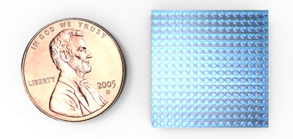
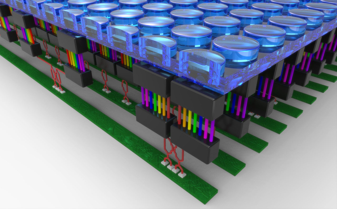
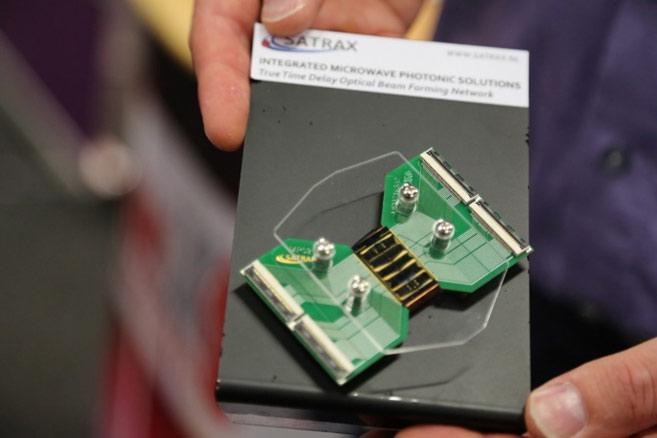
“So we convert the RF signal into light beams on an optical carrier, introduce a delay and then convert the signal back to a radio signal for distribution in the plane. It is done with a so-called optical beam forming network. You can do that on the photonics chip we’ve developed which has very low loss waveguides. These waveguides interact with ring-resonators which allow you to introduce the delay. The system tracks the geostationary satellite during the flight, calculates the off-set angle and so understands exactly what delays needs to be introduced to maximizes signal reception. The micro-ring-resonator can be tuned continuously. So the antenna is able to accurately track a signal source without having to physically turn the receiving antenna to point at the satellite.”
“This approach means you can make these antennas flat and very energy efficient. But the biggest advantage is the bandwidth that’s possible. The satellite operator gives you the option of tapping in to any channel between 10.75 GHz and 12.75 GHz, and each channel is around 40 MHz wide. So that gives a capacity of 100 channels when the two types of vertical and horizontal polarisation are taken into account. Each channel is about the equivalent of the bandwidth needed to transmit 8 high-quality broadcast television channels. At the moment, there is typically access to only one or two video channels on board an aircraft. Our satellite antenna technology increases that by a factor of 50.”
Integration takes time and serious money
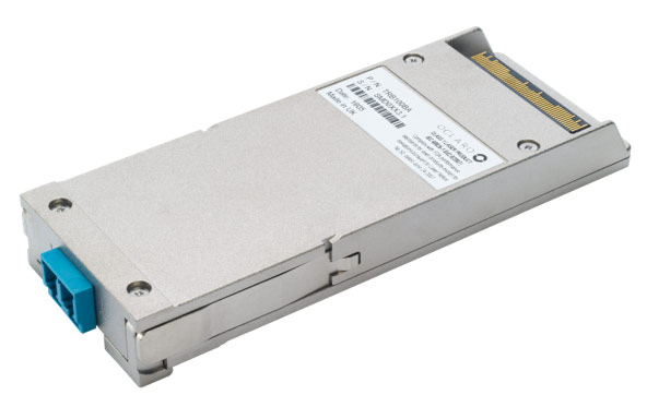
“We made our first version in 2007. The antenna was quite compact, but all the conversion and processing turned out to be a major “big box”. Each module in the receiving system was separate; the RF-to-optical converter, processor for the optical domain and then the conversion back to RF. Now you can hold that entire module in your hand.”
“Photonics integration allowed us to miniaturise things, but it doesn't come cheap. To give you an example. To bring this antenna processing unit down in size to a point where its commercially interesting, we needed to involve 8 companies. It cost us €3.2 million just to produce the first integrated prototypes. It is not something you can do with lean-engineering coupled with a few cycles of trials and improvements. But this is state of the art engineering. And it is key to providing future breakthroughs. There are no short cuts.”
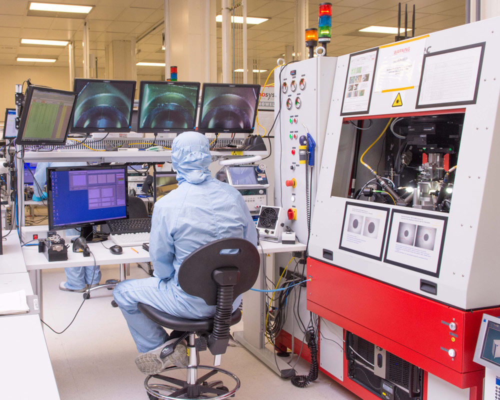
“You not only have to make the optical chips. You also have to assemble (or package) the chips onto a larger system board. Most of the assembly tolerances are a factor of 10 beyond what is currently possible with automated assembly systems which pick and place components. That explains why we are manually producing and assembling individual chips in Enschede. Some of our partners are now testing them in the field in places like Korea and China.”
“Everyone wants to solve the problem of more bandwidth for less cost and with a small footprint of components. We have competitors but they either have less bandwidth or a much bulkier system. They may be ahead of us in terms of a technical-readiness level, but this technology is designed for the longer term. And what we already learned in developing the aircraft antenna has direct connections with the work on energy efficient 5G mobile base stations.”
“There is also a market for optical links between satellites. Unless you're in the path of the beam, these connections are "unsniffable" and in space there is nothing like fog or cloud to attenuate or obscure the light signal. The only challenge is that you need a 250+ watt laser to bridge the distance, and we haven't put that on a chip just yet. I believe that TU Delft is looking into it for their Nanosat project. Our technology is also relevant for the nanosat receiving antennas with more accurate positioning for a lower cost.”
The importance of an end to end ecosystem
“SATRAX started as a product company with LioniX being the supplier of the TriPleX waveguide wafers, together with software suppliers like PhoeniX and assembling from Xio Photonics. We have a license from OctroliX to use the intellectual property for phased array antennas.”
“But when you reach a milestone that requires a major VC investor, they tend to want everything combined into one company. Which explains why we recently combined forces. LioniX, SATRAX, XiO Photonics and OctroliX have been rolled into one company called LioniX International. It is jointly funded by the Panthera Group based in Enschede together with our Korean partner YMK Photonics Co., Ltd. The focus of LioniX International will be on Photonic Integrated Circuits (PIC) enabled modules based on its proprietary waveguide technology (TriPleX™), in addition to its other core competencies microfluidics, optofluidics and MEMS. Basically, it is a complete chain - from initial design through to volume manufacturing of products.
Everything in close proximity
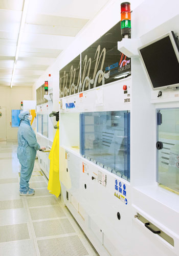
“R&D is well established in Enschede. All the parts needed to make a TriPleX ecosystem are together - and the cleanroom of the University of Twente is within walking distance. You need everything and everyone together when you're doing such complex R&D. There is a strong regional drive to keep that competence, capability and drive in the Enschede very close to the NanoLab. You need that for a quick turnaround time for customised products. We're in the process of rolling out some applications that will go to volume and for that, we need a factory that can handle volume production.”
“At one time we thought that would be in Dortmund, Germany, but now our Korean partners have stepped forward. They have access to a volume production factory. So we're working out what we need to do in terms of technology transfer so we can do volume production there.”
“Our partners are naturally keen to start as soon as possible. It is going to take around 18 months for us to reach technical readiness 5/6 (ready for manufacture). I think the fact that the Winter Olympic Games are being held in 2018 in Korea would be an excellent opportunity to showcase this breakthrough type of Photonics technology. And 3 years after that, the Summer Olympics will be in Japan, home to NTT DoCoMo.”
PhotonDelta
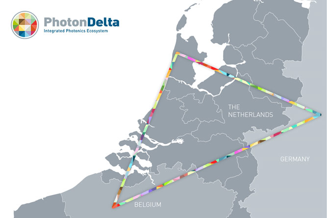
“I have been working at ASML for 11 years as a product manager until 2010, back then it was a technology triangle between Leuven, Aachen and Eindhoven. Today, the “photonics delta” stretches from Gent in the South, Alkmaar in the North, and through Eindhoven to include Enschede. You have everything within this area to make it happen with ready-for-market InP and lowest loss TriPleX. We can maintain a lead if we continue to look for synergies and combine efforts.”


